In modern vehicles and embedded systems, the CAN BUS and LIN protocol serve crucial but distinct roles. This article offers a deep technical comparison of CAN vs LIN, covering architecture, data rates, reliability, topology, real world stats and key people associated with these protocols. CAN is typically implemented in systems requiring high speed, robustness and error handling, such as ECUs and safety features. LIN, on the other hand, is designed for simpler, cost-sensitive subsystems such as window regulators and seat adjusters.
Table of Contents
Protocol Origins
The development of both CAN and LIN protocols marked major milestones in automotive communication. While CAN protocol was introduced earlier and aimed at mission-critical applications, LIN emerged as a simpler, cost-effective complement for non-critical subsystems.

| Feature | CAN Bus | LIN Bus |
|---|---|---|
| Initial Development | 1983 | Late 1990s |
| Key Contributors | Uwe Kiencke, Siegfried Dais, Martin Litschel (Robert Bosch GmbH) | LIN Consortium: BMW, VW, Audi, Volvo, Mercedes Benz, Motorola |
| First Public Introduction | February 1986 at SAE Congress, Detroit | Version 1.3 released in November 2002 |
| First Controller Chips | Intel 82526 and Philips 82C200 (1987) | Incorporated into microcontrollers developed by LIN Consortium members |
| First Production Car Implementation | Mercedes Benz W140 (1991) | Widely adopted in body electronics by mid-2000s |
| Standardization | ISO 11898 | ISO 17987, ANSI/SAE J2602 |
Architecture & Topology of CAN vs LIN
The core differences between CAN vs LIN protocol extend beyond their speed and use cases. Their underlying network structures, physical layers and message formatting approaches determine how each protocol is deployed in automotive and embedded systems.


| Main Feature Category | Sub-Feature | CAN Bus | LIN Bus |
|---|---|---|---|
| Data Rate and Bandwidth | Maximum Data Rate (Standard) | Supports up to 1 Mbit/s (Classical CAN). | Supports up to 19.2–20 kbit/s. |
| Maximum Data Rate (Extended/FD) | CAN FD allows data phase up to 5–8 Mbit/s, depending on system timing and transceiver capability. | Not applicable; LIN does not support extended data rates. | |
| Arbitration Speed | Arbitration is limited to 1 Mbit/s to maintain compatibility across all nodes. | No arbitration mechanism; master-slave timing controls communication. | |
| Bus Length Constraints | Bus length depends on baud rate; up to 40 meters at 1 Mbit/s (typical value). | Maximum recommended length is approximately 40 meters. | |
| Data Payload | Up to 8 bytes (Classical CAN) or 64 bytes (CAN FD). | Supports 2, 4 or 8 bytes depending on frame format. | |
| Network Structure | Architecture Type | Multi-Master configuration. | Single-master with up to 15 slaves. |
| Communication Control | Event-driven, where any node can initiate communication. | Time-triggered communication scheduled by the master node. | |
| Arbitration Method | Non-destructive bit-wise arbitration based on frame ID priority. The lowest CAN-ID (highest priority) wins without collision. | No arbitration; communication is deterministic and fully controlled by the master. | |
| Node Count Limitations | Theoretically unlimited, but practically limited by bus load and electrical parameters. | Maximum of 16 nodes (1 master + 15 slaves). | |
| Physical Layer and Wiring | Signal Type | Differential signal using a twisted pair of wires (CAN High and CAN Low). | Single-wire communication with reference to ground (GND). |
| Termination | 120-ohm (Ω) termination resistors at each end of the bus. | No termination resistors required; uses pull-up resistors. | |
| Resistor Configuration | Typically uses two 120-ohm resistors in parallel. | 1 kΩ pull-up at master, 20–30 kΩ at slave nodes. | |
| EMI Immunity | High EMI resistance due to differential signaling and termination. | Lower EMI immunity; more susceptible to noise due to single-wire topology. | |
| Power Consumption | Higher due to continuous operation and transceiver requirements. | Low power; includes sleep and wake functionality for energy-efficient subsystems. | |
| Connector and Cabling | Uses shielded/unshielded twisted pair with standard automotive connectors. | Uses simpler and cheaper single-wire cabling. | |
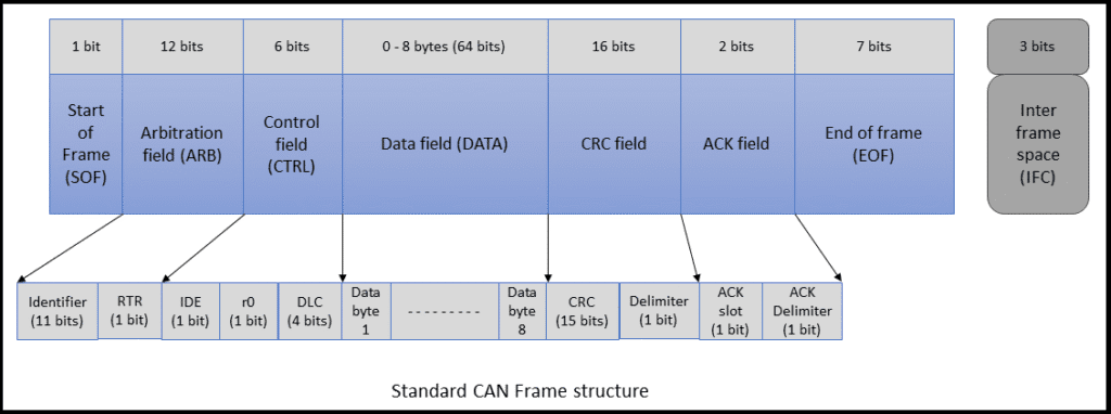
| Message Framing and Identifiers | Identifier Size | 11-bit (Standard Frame) or 29-bit (Extended Frame). | 6-bit identifiers. |
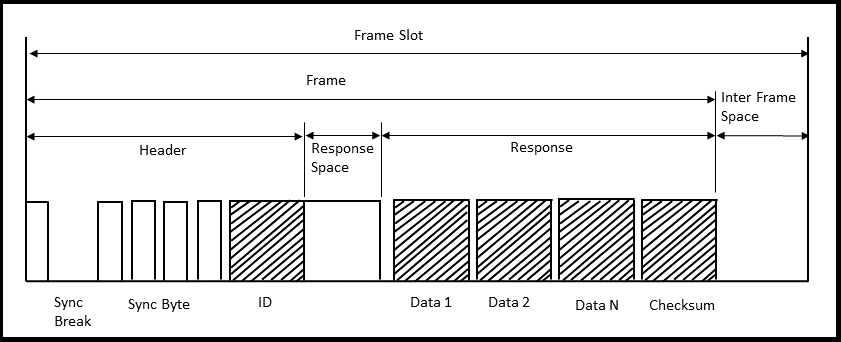
| Frame Components | Includes Start of Frame, Arbitration, Control, Data, CRC, ACK and End of Frame fields. | Includes Break, Sync, Identifier, Data field (2/4/8 bytes) and Checksum. | |
| Data Field Size | 0–8 bytes (Classical CAN), 0–64 bytes (CAN FD). | Fixed sizes of 2, 4 or 8 bytes depending on application. | |
| Synchronization | Synchronized using bit timing segments and sample points. | Uses break and sync fields for synchronization at the beginning of the message. | |
| Checksum Method | CRC-15 for Classical CAN; CRC-17 or CRC-21 in CAN FD. | Classic Checksum (8-bit sum) or Enhanced Checksum (including identifier byte). | |
| Addressing | Based on message IDs, not node addresses; supports broadcast and selective communication. | Addressing based on predefined identifier values; each slave responds only to specific IDs. |
Error Handling & Reliability in CAN vs LIN
Error management is a critical factor in determining the reliability of in-vehicle communication networks. CAN vs LIN differ significantly in their error detection and correction mechanisms, reflecting their intended use in safety-critical versus non-critical systems.
| Feature | CAN Bus | LIN Bus |
|---|---|---|
| Error Detection Methods | Implements multiple error-checking mechanisms including Cyclic Redundancy Check (CRC), bit monitoring and frame checks. | Uses a simpler error detection model with checksum verification and header parity checks. LIN lacks retransmission and complex error recovery. |
| Error Signaling | Faulty messages trigger automatic error frames. All nodes on the network are notified of the disturbance. | Limited signaling. Detected errors typically only affect communication between master and slave. |
| Acknowledgment System | Each transmitted message must be acknowledged by at least one receiving node. If no acknowledgment is received, the message is re-transmitted. | No acknowledgment system. The master assumes reception unless explicitly designed to detect issues. |
| Retransmission Handling | Messages with errors are automatically re-transmitted until successful or until the node exceeds the error threshold. | LIN does not support retransmission. Faulty messages are ignored and must be resent by the master. |
| Fault Confinement | Includes a built-in error counter that can isolate faulty nodes. A node can enter passive or bus-off states to protect network integrity. | Lacks advanced fault confinement. Faulty nodes may continue to interfere until addressed externally. |
| Overall Reliability | High reliability suitable for safety-critical and real-time control systems. | Moderate reliability suitable for non-critical body and comfort electronics. |
Use Cases and Applications
CAN vs LIN protocols serve different functional roles in modern automotive architecture. While CAN is optimized for real-time, high-reliability communication in critical control systems, LIN is tailored for cost-effective, low-speed control of body and comfort functions. Below is a detailed breakdown of their respective use cases, with each functional domain separated for clarity.
| Category | Sub-Feature | CAN Bus | LIN Bus |
|---|---|---|---|
| Automotive Systems | Powertrain Control | Used in engine management systems, transmission control units, turbo control and fuel injection systems. | Not applicable; LIN is not designed for real-time or high-performance powertrain tasks. |
| Chassis and Braking Systems | Deployed in Anti-lock Braking Systems (ABS), Electronic Stability Programs (ESP), and suspension control. | Not applicable. | |
| Safety Systems | Integral for airbag control, crash detection, seat-belt pretensioners, and driver-assistance systems. | May be used to control seat-belt warning lights or status indicators but not active safety components. | |
| ADAS | Handles radar, lidar, camera communication, and sensor fusion for features like adaptive cruise control. | Not applicable due to speed and bandwidth limitations. | |
| Diagnostics and Flashing | Enables Unified Diagnostic Services (UDS), CCP, and remote ECU flashing via OBD-II or OEM tools. | Used for basic local diagnostics, often via the master LIN node. | |
| Body and Comfort Features | Window and Mirror Control | Sometimes used when multiple features are integrated (e.g., memory seats with diagnostics). | Ideal for window lifts, mirror adjustment, and folding mechanisms. |
| Seat Adjustment and Heating | CAN may be used in premium systems with advanced memory and multiple actuators. | LIN commonly handles simple seat movement, recline, and heating functions. | |
| Interior Lighting and Ambient Features | Used when lighting is dynamic or part of an intelligent control scheme. | Widely used for dome lights, ambient light, and dashboard illumination. | |
| Sunroof and Wiper Control | CAN is used for automated systems with rain/light sensors. | LIN supports motor control and basic switches for manual sunroof or wiper operation. | |
| HVAC Control | CAN manages climate zones, temperature sensors, and compressor systems in higher-end models. | LIN handles actuator motors, air vent direction control, and fan speed in simpler systems. | |
| Network Architecture | ECU Distribution | A modern vehicle may have 60–70 or more Electronic Control Units (ECUs) connected via CAN or CAN FD. | Vehicles typically include 10 or more LIN clusters, each with multiple slave nodes. |
| Node Count per Vehicle | Total node count can exceed 100, especially in luxury vehicles with CAN FD integration. | Many vehicles have over 100 LIN nodes across all subsystems. | |
| Deployment Volume | Standard in virtually all modern vehicles; also used in commercial trucks and industrial machinery. | Over 600 million LIN nodes were deployed in vehicles by 2020. | |
| Use in Other Industries | Used in medical devices, industrial automation, marine electronics, and aerospace applications. | Common in white goods (e.g., washing machines), home appliances, and basic industrial controls. |
Final Thoughts
CAN vs LIN serve complementary roles in automotive and embedded environments. CAN Bus is preferred for high speed, fault tolerant, mission critical communications. LIN provides an inexpensive way to control comfort and body systems with minimal wiring and simple hardware.
Combined wisely, they enable flexible, scalable and cost effective vehicle networks. In a typical vehicle architecture, systems such as engine control, transmission, and adaptive braking rely on CAN due to its robust error handling and higher data rate, which ensures real time responsiveness and system integrity.
For example, a CAN based Electronic Stability Control (ESC) system can process sensor inputs and transmit corrective commands in under 10 milliseconds. On the other hand, LIN is better suited for applications like seat position adjustment or interior lighting, where latency is not critical and the cost of adding a full CAN transceiver would be unjustified.
Moreover, many OEMs integrate LIN clusters through gateway ECUs that relay data back to the main CAN bus, thus optimizing bandwidth allocation and reducing software complexity. As automotive networks evolve toward zonal architectures and service oriented communication, the coexistence of CAN and LIN will continue to play a key role in balancing performance, reliability and manufacturing cost.


