
Automotive Ethernet is rapidly emerging as the backbone of next-generation vehicle communication, replacing legacy networks with faster and smarter data pathways. As cars evolve into intelligent, software-defined machines, this in-vehicle network enables the seamless flow of high-bandwidth information that modern mobility now demands.
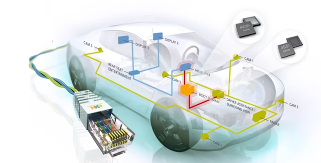
Table of Contents
What is Automotive Ethernet?
It’s a new Ethernet PHY physical layer designed specifically for the Automotive domain. It is developed by Broadcom.
It enables high-speed in-vehicle communication using a lightweight single pair of wires, reducing cable weight and cost. Automotive Ethernet is now widely used for cameras, sensors, ADAS ECUs, infotainment and domain controllers.
nBASE-T(x), where, T = Twisted Pair
Institute of Electrical & Electronics Engineers (IEEE) defines global communication standards and Automotive Ethernet falls under IEEE 802.3 specifications. These standards ensure interoperability between different vendors and guarantee performance and reliability for automotive data networks. Example: 802.3, 802.11, 802.1AS, 802.bla.bla
Types of Automotive Ethernet Standards
Conventional Ethernet
10BASE-T → Original 10 Mb/s copper Ethernet. No “X” after “T”. This was primarily used in early LAN networks, offering very low bandwidth by today’s standards. Its structure laid the foundation for later BASE-TX and BASE-T1 technologies.
100BASE-TX → Called “FAST ETHERNET” at launch, not fast anymore. “X” is required, which led to lots of confusion since it’s only used here. It became extremely popular in the 1990s and early 2000s, offering enough bandwidth for basic data communication before Gigabit Ethernet became standard.
1000BASE-T → Gigabit Ethernet (“no X” here). This standard supports 1 Gb/s over four twisted pairs and is still widely used in computers, switches, and routers. It provides high throughput but isn’t suitable for automotive constraints without modification.
10GBASE-T → Above Gigabit. IEEE started using “G” for Gigabit, so this is 10 Gb/s. 10GBASE-T provides enterprise-level performance but is too power-hungry and complex for most automotive applications. However, it influenced the development of high-speed automotive PHYs.
Auto-negotiation (10/100/1000) → Sometimes you will see multiple speeds like “10/100” or “10/100/1000” — This means the device can auto-negotiate any of these speeds. Autonegotiation allows devices to determine the highest common speed supported, increasing compatibility across network equipment.
Automotive Ethernet
BroadR-Reach → The original single-pair Automotive Ethernet made by Broadcom. Sometimes used with trademark symbol (®). It was developed to reduce wiring bulk and support 100 Mb/s communication over a single unshielded twisted pair (UTP). BroadR-Reach became the foundation for many modern automotive networking architectures.
100BASE-T1 → The IEEE version of BroadR-Reach. Nearly identical to BroadR-Reach but not identical. It standardizes the PHY layer for 100 Mb/s over a single pair and ensures multi-vendor interoperability. This is now widely adopted in ADAS, cameras, and gateway ECUs.
1000BASE-T1 → The new Gigabit single-pair Automotive Ethernet. No Broadcom equivalent. It supports 1 Gb/s data rates over a lightweight single pair, enabling high-bandwidth applications like surround-view cameras, radar processing, and central compute architecture in modern vehicles.
Networking fundamentals
Packet switching → Packet switching divides data into independent packets that travel through the network using dynamically chosen routes, improving flexibility, performance, and bandwidth utilization.
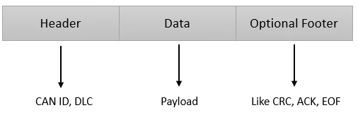
Frame formatting → Networking protocols define specific frame structures that organize headers, payload data, and optional footers such as CRC, ACK, or EOF for error handling.
Message addressing methods → Automotive Ethernet uses unicast (1→1), broadcast (1→all) and multicast (1→many) addressing to efficiently distribute messages across the vehicle network.
Networking topologies → Common topologies include point-to-point, ring, bus and star configurations, each influencing network robustness, redundancy, and wiring complexity.
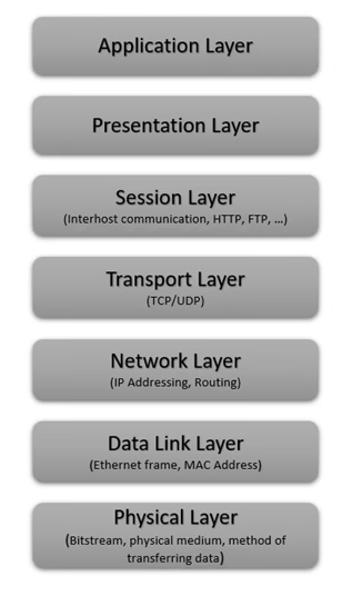
OSI Layers of Automotive Ethernet
The OSI layers in Automotive Ethernet provide a structured framework that defines how data moves from the physical wiring in a vehicle to the highest-level software applications. By standardizing functions across seven layers i.e. from the Physical and Data Link layers up to the Application layer, they ensure reliable, interoperable, and secure communication between automotive ECUs and networked systems.
Physical Layer
The physical layer defines the electrical and hardware characteristics of the network, including how bits are transmitted and received; Example: components like CAN transceivers fit here.
The Physical Layer is responsible for transmitting raw bit streams over the physical medium, ensuring that electrical or optical signals correctly represent digital data. It defines the wiring, signaling, and encoding methods used to move information across the network.
10BASE-T, 100BASE-TX -> These standards use two twisted pairs (four wires) to carry data and operate in full-duplex mode, allowing simultaneous send and receive operations. They are widely used due to their reliability and compatibility with existing automotive test equipment. Their simplicity also makes them suitable for lower-bandwidth in-vehicle communication needs.
1000BASE-T (Gigabit Ethernet) -> This standard uses four twisted pairs (eight wires) and supports full-duplex transmission, enabling much higher throughput than earlier variants. It is designed for applications that require large data transfers, such as ADAS sensors or high-resolution cameras. Gigabit Ethernet offers a scalable path toward future high-speed automotive networks.
Ethernet Node
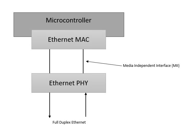
An Ethernet node consists of a microcontroller, an Ethernet MAC controller and a PHY Ethernet layer.
The MAC communicates with the PHY through an industry standard digital connector called Media Independent Interface (MII). MII enables different PHYs to be connected or used with any MAC.
Because MII is standardized, it allows engineers to mix and match different PHYs with any MAC, offering flexibility in system design. This architecture supports full-duplex Ethernet, ensuring efficient bidirectional communication in automotive systems.
Media Converters
Media converters convert between different PHY-layer implementations of the same network, allowing incompatible Ethernet types to communicate.
They are commonly used in Automotive Ethernet environments to bridge BroadR-Reach (1-pair automotive Ethernet) with conventional 4-wire Ethernet used in laptops and test equipment. Devices like Intrepid Control Systems’ RAD Moon provide this conversion, making diagnostics and development significantly easier.
Data Link Layer
This layer manages Media access control (MAC), Low-level device addressing, Low-level message formatting and low-level error detection. Example: CAN controllers and VLANs operate at this level.
The Data Link Layer includes Ethernet frame handling and MAC addressing, serving as the foundation for reliable node-to-node communication. It defines how data is structured into frames and how each device on the network is uniquely identified.
Ethernet Frame format
An Ethernet frame can carry 46 to 1500 bytes of payload data.
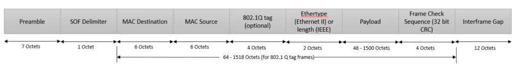
- Ethernet frame size (minimum): 64 bytes (+4 bytes optional VLAN) → 68 bytes i.e. (6+6+2+46+4) or (6+6+4+2+46+4)
- Ethernet frame size (maximum): 1518 bytes (+4 bytes optional VLAN) → 1522 bytes i.e. (6+6+2+1500+4) or (6+6+4+2+1500+4)
These sizes include headers, payload and error-checking fields. Consistent frame length is important to ensure collision detection and proper synchronization across the network.
1 Octet = 8 bits (1 byte)
Preamble
The preamble is a 7-byte sequence of alternating bits (10101010) that allows network clocks to synchronize before actual data transmission begins. This ensures that both sender and receiver are aligned at the bit level. Without proper synchronization, data could be misinterpreted, leading to communication errors.
Start of Frame (SOF) Delimiter
The SOF is a 1-byte sequence (10101011) indicating that the actual Ethernet frame is about to begin. It acts as a marker separating synchronization bits from the meaningful header fields. This helps receivers detect the start of the structured data.
MAC Address (Source and Destination)
A MAC address is 6 bytes long, globally unique and assigned to every network interface. The first three bytes are registered to an organization/manufacturer i.e. OUI bytes (Organizationally Unique Identifier). Special addresses, such as broadcast MACs, enable frames to reach multiple devices at once. In Ethernet networks, MAC addresses ensure that data is delivered to the correct destination.
VLAN Tag (802.1Q)
A VLAN tag is a 4-byte optional field used by protocol to Isolate networks and control bandwidth. It contains a VLAN IDentifier and priority information, helping protocols like Audio Video Bridging (AVB) guarantee time-sensitive traffic delivery.
EtherType
EtherType is a 16-bit (2-byte) field that identifies the type of payload being carried or, in some cases, its length. It enables switches and protocol stacks to determine how to interpret the following data.
Protocols such as AVB and TCP/IP use EtherType to ensure frames are processed correctly.
Payload
The payload contains the actual Ethernet data, holding information from higher-layer protocols or applications. Its size (46 – 1500 Octets) can vary depending on the frame type. In vehicles, payloads often carry sensor data, diagnostics information or control messages.
Frame Check Sequence (FCS) / CRC
The 32-bit CRC in the Frame Check Sequence verifies the integrity of the frame by detecting transmission errors. If a frame fails the CRC check, it is discarded by switches or controllers. Unlike CAN, Ethernet has no built-in retransmission, so reliability depends on higher-layer protocols such as TCP.
Interframe Space (IFS)
The interframe space is a 12-byte gap between consecutive Ethernet frames. It ensures devices have enough processing time before receiving the next frame. This spacing maintains stability and prevents collisions in busy networks.
Ethernet MAC Address
A MAC address directs data to the correct device on an Ethernet network, acting as a low-level physical identifier. It is programmed into the network hardware but can be modified temporarily or permanently using MAC spoofing.
All IEEE 802.x protocols, including Wi-Fi, rely on MAC addresses. In Automotive Ethernet, “MAC Address = Ethernet Address”.
Types of Ethernet Messages
Broadcast Messages
These use a MAC address of ‘FF:FF:FF:FF:FF:FF’, instructing all devices on the network to process the frame. Broadcasts are typically used for discovery or initialization processes. In a large network, excessive broadcasts can cause unnecessary traffic.
Multicast Messages
Multicast addresses begin with ’01’ in the first byte, allowing only selected devices to accept the frame. They are widely used for protocol-specific communication, such as streaming data or vendor-specific services. Multicast reduces unnecessary traffic by targeting only relevant receivers.
Unicast Messages (Point-to-Point)
Unicast addresses begin with ’00’ and direct the frame to a single specific node. This is the most common form of communication in automotive networks. Unicast messages support reliable, targeted data delivery for critical functions.
Network Layer
The network layer handles Logical device-level addressing, routing, universal encapsulation and packet fragmentation and reassembly. Example: standards like ISO 15765-2 ‘long-message’ handling, internet protocol (IP), internet control message protocol (ICMP).
Transport Layer
It provides end-to-end communication through logical connections, multiplexing, de-multiplexing, ACK, flow control and protocols like TCP and UDP; automotive protocols such as GMLAN, UDS, ECU addressing operate here.
Session Layer
The session layer establishes and manages communication sessions between ECUs and diagnostic tools, including functions like Diagnostic sessions (Tester Present, extended diagnostics sessions, cybersecurity) and J2534 passthru scan APIs; CAN Calibration Protocol (CCP) also fits here.
Presentation Layer
This layer ensures data is formatted correctly (“presentation”) for communication by handling translation, compression & decompression, encryption & decryption; while unlocking doesn’t occur here, network-level data encryption aligns with this layer’s responsibilities.
Application Layer
The application layer delivers vehicle-level network services such as diagnostics, flashing and telematics via protocols like HTTP, DPS, WinValid, GDS, DET and CDA.
