SAE J1939 is a high-layer protocol based on the CAN network. It is used in trucks, buses, earth moving machines and heavy-duty vehicles for in-vehicle networking and diagnostics. SAE J1939 is also used in agriculture and forestry machinery (ISO 11783), military vehicles (MiL CAN), ships, rail vehicles, and marine navigation systems (NMEA 2000).
Table of Contents
Overview of SAE J1939
SAE J1939 is a set of standards defined by the Society of Automotive Engineers (SAE) for communication and diagnostics among vehicle components. This protocol is based on the CAN protocol. SAE J1939 does not support master / slave or client / master architecture. SAE J1939 uses 29 bit CAN identifier for message frames and 250 kbit/second (some running at 500 kbit/sec) baud rate.
Network management defined in SAE J1939/81 allows a maximum of 30 notes in a network. SAE J1939 messages use the CAN 2.0B physical layer. It allows 11 bit CAN messages to be sent as proprietary messages on bus. Before transmitting messages on bus, each node must claim a one byte network address. Maximum bus length is 40 m and maximum note count is 30. SAE J1939 consists of a shielded twisted pair of wires and the shield is connected directly to the ground.
There are three different types of SAE J1939 communication i.e. Destination specific (peer-to-peer), Broadcast and Proprietary. SAE J1939 protocol is mainly used in heavy duty vehicles, like trucks, buses, excavators, diggers, cranes, ships, rails, military vehicles etc.
SAE J1939 message frame format
SAE J1939 messages are structured in a specific format to ensure compatibility and interoperability with different types of vehicles. Lets understand the CAN frame format for SAE J1939 protocol:
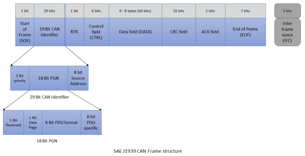
Priority field
It is of 3 bits. i.e. 2^3 = 2x2x2 = 8 different values. ‘000’ is the highest priority and ‘111’ is the lowest priority. High priority data messages are assigned to time critical data such as torque, control data from transmission to engine. Whereas, low priority messages are assigned for non critical data such as engine configuration data.
Parameter Group Number (PGN)
PGN stands for Parameter Group Number and identifies the parameter group (PG). It is 18 bits long. Parameter Groups point to the information of parameter assignment within 8 bytes of CAN data field, repetition rate and priority. There are 8672 different Parameter Groups per page and 2 pages are available.
Source Address
It is 8 bits long i.e. 2^8 = 256 different addresses available. These are the last 8 bits of a 29 bit CAN identifier value. Source address means it is the address of the transmitting (Tx) ECU.
Reserved
This field is reserved for future purposes and is one bit long. It should always be set to ‘0’ for J1939 when transmitting messages.
Data Page
It is 1 bit long and identifies the page (0 or 1) that a message belongs to. It is a page selector for the PDU (Protocol Data Unit) format field. Currently it is set at 0 and 1 (i.e. Page 1) is reserved for future use. 0 value means it points to page 0. Data page is used to increase the number of available PGNs. Most of the PGNs are on page 0.
PDU Format
It is 8 bits long i.e. 2^8 = 256 different values (0 – 255).
PDU format values 0 – 239 (i.e. PDU 1) are destination specific. PDU1 indicates a destination address in the PDU Specific field.
PDU format values 240 – 255 (i.e. PDU 2) are Broadcast. PDU 2 indicates an extension to PDU format. It is used for data that is meant to be broadcast on a regular and defined interval.
PDU Specific
It is 8 bits long. Its content is interpreted according to information in the PDU format field.
Example of PGN
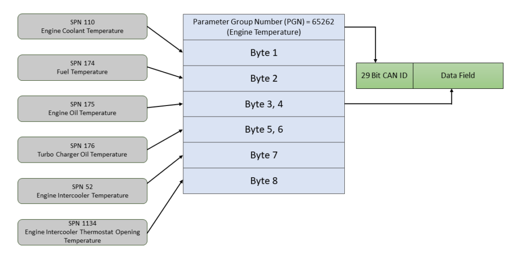
Lets take an example: PGN 65262 (0xFEEE)
Priority = 6
Reserved = 0
Data Page = 0
PDU Format = 254
PDU Specific = 238
NOTE: PGN’s least significant byte is always 0x00 for PDU 1 i.e. PGN of 0xEF01 would never be a valid PDU1.
PGN Range
| Data Page | PGN Range (hex) | Number of PGNs | SAE or Manufacturer assigned | Communication |
|---|---|---|---|---|
| 0 | 0x000000 – 0x00EE00 | 239 | SAE | PDU1 = Peer to Peer |
| 0 | 0x00EF00 | 1 | Manufacturer | PDU1 |
| 0 | 0x00F000 – 0x00FEFF | 3840 | SAE | PDU2 = Broadcast |
| 0 | 0x00FF00 – 0x00FFFF | 256 | Manufacturer | PDU2 |
| 1 | 0x010000 – 0x01EE00 | 239 | SAE | PDU1 |
| 1 | 0x01EF00 | 1 | Manufacturer | PDU1 |
| 1 | 0x01F000 – 0x01FEFF | 3840 | SAE | PDU2 |
| 1 | 0x01FF00 – 0x01FFFF | 256 | Manufacturer | PDU2 |
SAE = Assigned by Society of Automotive Engineers
Manufacturer = Manufacturer specific i.e. proprietary messages
History of SAE J1939
The development of SAE J1939 began in the late 1980s aiming to create a communication protocol for heavy-duty vehicles. In 1988, initial development of SAE J1939 protocol started. By the year 1994 first official release of SAE J1939 standard was released. In 2000s decade, SAE J1939 was integrated with other protocols and its functionalities were expanded. By 2010s, SAE J1939 was adopted for a broader range of industries and vehicles like Agriculture, Military, rail and marine.
SAE J1939 Protocol Layers
SAE J1939 protocol follows the OSI model, with specific layers designed for automotive applications.
Physical Layer
The physical layer of SAE J1939 uses the CAN bus, which provides a robust and reliable communication medium.
Data Link Layer
The data link layer ensures error detection and message framing, utilizing the CAN protocol’s inherent capabilities.
Network Layer
The network layer manages the addressing and routing of messages between different ECUs.
Transport Layer
The transport layer handles the segmentation and reassembly of larger messages that exceed the CAN frame size.
Application Layer
The application layer defines the specific messages and parameters for various vehicle functions.
Key features of SAE J1939
Key features of SAE J1939 include:
- CAN-Based Protocol: SAE J1939 is based on the Controller Area Network (CAN) protocol, specifically utilizing the high-speed CAN (CAN-H) communication network. This allows for reliable and efficient data exchange between electronic control units (ECUs) in a vehicle.
- Message Format: SAE J1939 defines a standardized message format for transmitting data and control information. Each message contains an identifier (PGN – Parameter Group Number), priority, source address, destination address, and payload data.
- Parameter Group Numbers (PGNs): PGNs are used to categorize different types of data, such as engine speed, vehicle speed, fuel level, and more. Each PGN is associated with specific data and has a unique identifier for identification.
- Addressing: SAE J1939 uses 29-bit CAN identifiers to support a large number of ECUs and devices on the network. This allows for extensive scalability and flexibility in building complex vehicle systems.
- Diagnostic Capabilities: SAE J1939 includes diagnostic services that enable communication between onboard diagnostic systems and external diagnostic tools, facilitating vehicle troubleshooting and maintenance.
- Transport Protocol: For large data packets that cannot fit into a single CAN message frame, SAE J1939 employs a transport protocol to break the data into smaller segments and reassemble them at the receiving end.
- Multiple Network Topologies: SAE J1939 supports various network topologies, including star, daisy-chain, and mixed topologies, allowing manufacturers to design vehicle systems according to their specific requirements.
Applications of SAE J1939
SAE J1939 is used in a variety of applications across different industries.
Heavy-Duty Vehicles
In heavy-duty vehicles, SAE J1939 enables communication between the engine, transmission, brakes, and other critical systems.
Agricultural Equipment
In agricultural equipment, it facilitates the integration of various sensors and actuators for efficient operation.
Construction Machinery
In construction machinery, it supports the control and monitoring of hydraulic systems, engines, and other components.
Advantages of Using SAE J1939
There are several advantages to using the SAE J1939 protocol in vehicle systems.
Standardization
SAE J1939 provides a standardized communication protocol, ensuring compatibility between different manufacturers’ components.
Robustness
The protocol is designed to operate in harsh environments, making it ideal for heavy-duty applications.
Scalability
SAE J1939 can be scaled to accommodate different network sizes and complexities.
Challenges and Limitations
Despite its advantages, SAE J1939 also presents some challenges and limitations.
- The protocol’s complexity can be a hurdle for new developers and engineers.
- The CAN bus, which SAE J1939 relies on, has limited bandwidth, which can be a constraint in data-intensive applications.
Future of SAE J1939
The future of SAE J1939 looks promising, with ongoing developments aimed at enhancing its capabilities.
Integration with New Technologies
Efforts are being made to integrate SAE J1939 with emerging technologies like IoT and autonomous vehicles.
Enhanced Security
Future versions of the protocol will likely incorporate enhanced security features to protect against cyber threats.
Final Thoughts
SAE J1939 is a critical protocol in the automotive and heavy-duty vehicle industries, providing a standardized and reliable communication framework. Its widespread adoption and continuous evolution make it a cornerstone for vehicle networking, ensuring interoperability and efficient operation across various applications. By understanding the intricacies of SAE J1939, automotive professionals can leverage its capabilities to develop advanced and robust vehicle systems, paving the way for future innovations in the industry.
SAE J1939 is widely used in the commercial vehicle industry due to its robustness, reliability, and widespread adoption by vehicle manufacturers and suppliers. It enables seamless communication between various ECUs, allowing for efficient coordination of vehicle systems and the implementation of advanced functionalities such as engine control, transmission management, brake systems, and more. The standardization of SAE J1939 facilitates interoperability and compatibility between different vehicle components and systems, making it an essential part of the modern commercial vehicle electronic architecture.