
The CAN BUS is a serial communication protocol that enables microcontrollers to communicate with each other. Operating as a multi-master message broadcast system, CAN functions as a peer-to-peer network where all ECUs have equal rights to send messages over the CAN bus.
Table of Contents
First things first: What is an ECU?
An electronic control unit (ECU) is an embedded device inside a vehicle that controls a specific feature. Common examples of ECUs include the Engine Control Module (ECM), Powertrain Control Module (PCM), Transmission Control Module (TCM), Anti-lock Braking System (ABS), and Body Control Module (BCM), among others.
These electronic devices control the vehicle’s mechanical movable parts through software code running inside them. Modern cars can contain more than 100 ECUs.
These ECUs communicate with each other continuously over in-vehicle networks such as CAN, CAN-FD, LIN, Ethernet, FlexRay, and MOST. The automotive industry most commonly uses CAN as the in-vehicle network in modern vehicles.
What is CAN BUS protocol?
CAN is short for ‘controller area network’. CAN is an in-vehicle bus network that allows microcontrollers and ECUs to communicate with each other. The ISO 11898 standards define how CAN communication works, how to configure the wiring, and how to construct CAN messages. CAN is designed to handle high levels of electromagnetic interference and can provide reliable communication even in challenging environments.
CAN is a peer-to-peer network, i.e. all the ECUs have equal rights to send messages on the bus. The CAN Identifier sets the priority of the messages. The message with the lowest identifier has the highest priority and will be sent first. If 2 ECUs start transmitting simultaneously, the priority of the CAN-ID decides which ECU is permitted to send its message. This process, called bit-by-bit Arbitration, follows the CSMA/CA protocol. The maximum speed of a CAN bus is 1 Mbit/second according to the standard; however, this varies based on the CAN configuration used.
The CAN bus protocol has different configurations according to the wiring and voltage levels: high-speed CAN, Low-Speed CAN, and Single-Wire CAN (SWC). However, high-speed CAN is generally used and is called just CAN.
History of CAN BUS
The CAN bus protocol was developed by Bosch in the early 1980s to address the growing complexity of in-vehicle communication systems. Its development started in 1983 and was released in 1986 at the Society of Automotive Engineers (S.A.E.) conference in Detroit, Michigan.
After its introduction in 1986 CAN quickly gained traction for its robustness and efficiency. By 1991, the first production vehicles using CAN were released, setting a new standard for automotive communication.
CAN was developed because of the rising need for serial bus communication in vehicles to add new functionalities and to reduce the wiring harnesses. Over the years, CAN has evolved with enhancements like CAN FD and CAN-XL to meet increasing data throughput demands.
ISO Standards for CAN bus protocol
The CAN communication ISO standard is ISO-11898: 2003. Several standards define the CAN protocol and its implementation:
- ISO 11898-1: Specifies the data link layer and physical signaling of the CAN protocol.
- ISO 11898-2: Defines the high-speed physical layer for CAN.
- ISO 11898-3: Specifies the low-speed, fault-tolerant physical layer.
- ISO 11898-4: Defines the time-triggered communication in CAN.
How CAN BUS protocol works?
CAN is a message-based protocol that digitally transmits data via twisted pairs of copper wires with differential voltage. The CAN bus protocol operates on a message-based principle, where each message is assigned a unique identifier. This identifier determines the priority of the message, with lower values indicating higher priority. Information is sent via these fixed-format messages.
The CAN bus allows multiple nodes to communicate on the same network without any centralized control. Any ECU or node can send messages when the CAN bus is free. Each ECU can have many messages depending on the amount of information it has. A single CAN message can send a maximum of 8 bytes (8*8=64 bits) of data.
CAN message
Each ECU sends information to each other in the form of CAN messages. These messages contain the data. Since the CAN bus is broadcast, all nodes can hear all transmissions. Each CAN message has a unique CAN identifier (CAN-ID), redirecting a CAN message to a specific ECU. A CAN message can carry upto 8 bytes of data.
CAN identifier / CAN Arbitration ID
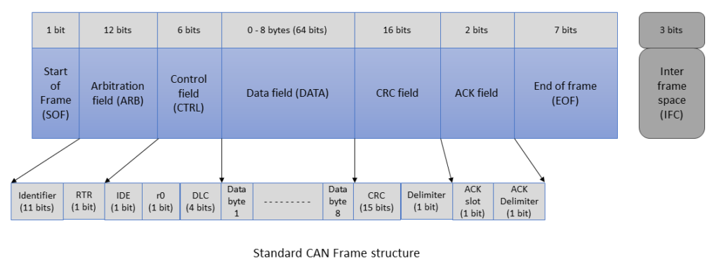
Each message has a unique Identifier (hexadecimal) called CAN-ID or CAN Arbitration ID. A CAN-ID uniquely identifies a CAN message. There are two types of CAN-IDs, i.e. Standard CAN and Extended CAN frames. A CAN message is structured like this:
Types of CAN bus messages
There are four types of CAN frames. They are:
1. Data Frame
A data frame is the most common frame in the CAN bus protocol. It contains data. All regular frames containing data are known as Data frames. A data frame consists of 7 fields.
2. Remote frame
If a node requires data from another node on the network, this can be achieved by sending a Remote Frame. For example – A comfort electronics ECU sends a remote frame to the powertrain ECU to know the state of the transmission gear (i.e. is the car in parking mode?). A remote frame is the same as a data frame, with two significant differences:
- It is explicitly marked as a Remote Frame by setting the RTR bit as recessive (1).
- There is no Data Field in the remote frame.
3. Error frame
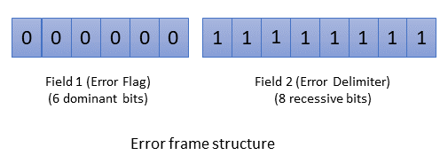
If a transmitting or receiving node detects an error, it will send an error frame and cancel the transmission. Error frame consists of an error flag made up of six dominant bits (000000) and an error flag delimiter made up of eight recessive bits (11111111).
Since this bit string violates the bit stuffing rule, all the other nodes also respond by transmitting error flags. After detecting sufficient errors, the node will eventually turn itself off.
There are two types of error flags – Active and Passive. Active error flags consist of 6 dominant bits (000000), and Passive error flags have six recessive bits (111111). The errors are calculated in a counter:
REC stands for Receive Error Counter and TEC is Transmit Error Counter.
When TEC/REC is greater than 255, the Bus is off
Passive error flags are set, when TEC or REC is greater than 127.
And, when TEC/REC < 128, then Active error flags are set
4. Overload frame
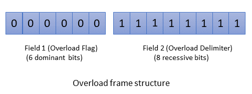
A CAN node uses an Overload frame to report an overload. It sends this frame when it receives messages faster than it can process, providing extra time between successive Data or Remote frames. Similar to an Error frame, the Overload frame has two fields as well: an overload flag consisting of six dominant bits (000000) and an Overload Delimiter consisting of eight recessive bits (11111111). Unlike error frames, overload frames do not increment error counters.
Bus Arbitration
Can the CAN Identifier set the priority of the message? The lower the CAN-ID (meaning lower hexadecimal number), the higher the message priority. Therefore, high-priority messages are reserved for safety-critical features like braking, steering, and Airbags. Example: A message with CAN-ID 0x001 has higher priority than one with 0x004 CAN-ID. Now, what is the benefit of high priority?
If 2 ECUs start a transmission simultaneously, the message’s priority decides which ECU sends the message first. This process, known as bit-by-bit arbitration, follows the CSMA/CA (Carrier-sense multiple access with collision avoidance) protocol.
Bit-rate or Baud rate of CAN bus
The CAN bit rate specifies how many bits can be transmitted over a CAN bus in a second. It defines the data rate or speed of the CAN network. CAN max speed is 1 MBits/sec (i.e. 1*1000*1000 bits = 1,000,000 bit = 125,000 Bytes = 125 KByte per sec). This is the max a CAN message can transmit in 1 second.
Implementing CAN TP (Transport Protocol)
The CAN TP (transport protocol) is a robust vehicle bus standard designed to allow microcontrollers and devices to communicate with each other without needing a host computer. Developed by Bosch in the 1980s, CAN is primarily used in automotive applications but has expanded into various other sectors due to its reliability and efficiency.
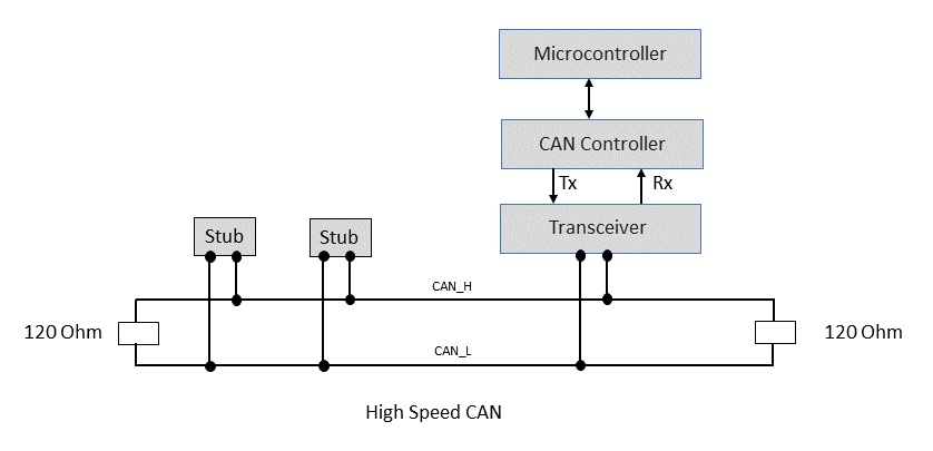
Hardware Requirements
To implement the CAN bus protocol, you need the following hardware components:
- Microcontroller with CAN Controller: Many modern microcontrollers have built-in CAN controllers.
- CAN Transceiver: Converts the digital signals from the CAN controller to differential signals required for the CAN bus.
- CAN Bus: A two-wire bus (CAN_H and CAN_L) that connects all nodes in the network. High-Speed CAN, Low-Speed CAN and Single Wire CAN are used as a physical medium.
Software Implementation
Implementing CAN communication involves configuring the CAN controller, setting up message filters, and handling the transmission and reception of messages. Many microcontroller manufacturers provide libraries and APIs to simplify the implementation process.
Key Features of CAN BUS Protocol
- Multi-Master Architecture: CAN supports multi-master nodes architecture. This allows any node to initiate the communication.
- Message-Oriented: Communication is based on messages rather than addresses, which enhances the flexibility of the network.
- Error Detection and Fault Confinement: CAN includes sophisticated error detection mechanisms and can isolate faulty nodes to maintain network integrity.
- High-Speed Communication: CAN can support communication speeds of up to 1 Mbits/s (Classical CAN) and even higher in newer versions like CAN FD (upto 8 Mbits/sec).
Further Developments
The CAN bus protocol continues to evolve, with ongoing developments aimed at enhancing its capabilities and expanding its applications. CAN FD (Controller Area Network with Flexible data rate) was introduced as an extension to the original CAN protocol. The standardization of CAN FD took place with the release of ISO 11898-1:2015, published in 2015. CAN FD is a significant step forward, offering higher data rates and larger data payloads.
Further, CAN in Automation (CiA) developed CAN XL (Controller Area Network extended data-field length). It is an addition to the existing CAN bus protocol to increase its bandwidth capabilities to over 10 Mbit/s.
Additionally, the integration of CAN with other communication protocols, such as Ethernet, is being explored to meet the increasing demands of modern applications.
The CAN protocol is a versatile and reliable communication standard that has become a cornerstone of automotive and industrial communication systems. Its robustness, flexibility, and real-time capabilities make it an ideal choice for various applications. As technology advances, the CAN BUS protocol will remain a vital communication tool, adapting to new challenges and requirements.
