
FlexRay is a high-speed and fault-tolerant communication protocol designed for modern automotive in-vehicle networks. It was developed as an alternative to CAN to meet the increasing demands for real-time communication and higher data bandwidth in ADAS & other safety-critical applications.
Table of Contents
What is FlexRay protocol?

FlexRay is a high-speed, deterministic, and fault-tolerant communication protocol designed specifically for automotive applications. It addresses the need for reliable and efficient data communication in modern vehicles, supporting real-time control and safety-critical systems.
FlexRay was developed by the FlexRay Consortium which included major automotive manufacturers and suppliers such as BMW, Bosch and Volkswagen. The protocol was designed to overcome the limitations of existing in-vehicle communication protocols like CAN and LIN protocol particularly in terms of speed, reliability, and fault tolerance.
Architecture of FlexRay
The FlexRay protocol is built on a time-triggered architecture, ensuring deterministic communication by synchronizing nodes to a global time base. The architecture of FlexRay is designed to provide high-speed, deterministic and fault-tolerant communication for automotive systems. FlexRay protocol is designed for data rates up to 10 Mbit/s.
Its architecture ensures synchronized and reliable data exchange across multiple nodes in the vehicle. The dual-channel design further enhances fault tolerance and robustness, making FlexRay suitable for safety-critical applications. The key components of the FlexRay architecture include:
Communication Controller
The Communication Controller is responsible for managing data transmission and reception within the network. It ensures that messages are sent and received according to the global schedule, maintaining synchronization across all nodes.
The controller handles both the static and dynamic segments of the communication cycle, facilitating deterministic and flexible data exchange. Additionally, it incorporates error detection mechanisms to ensure data integrity and reliability in the communication process.
Bus Guardian
The Bus Guardian plays a critical role in ensuring network integrity by monitoring and controlling access to the communication bus. It ensures that each node adheres to the predefined communication schedule, preventing any node from transmitting outside its allocated time slots.
This safeguard helps avoid collisions and ensures the deterministic nature of the network. Additionally, the Bus Guardian enhances fault tolerance by preventing faulty nodes from disrupting the overall network communication.
Physical Layer
The Physical Layer defines the electrical and mechanical characteristics of the communication medium, facilitating the actual transmission of data signals. It typically employs a dual-channel architecture, using two independent channels (Channel A and Channel B) to enhance fault tolerance and reliability.
This layer handles the encoding and decoding of data, converting digital signals from the Communication Controller into electrical signals for transmission and vice versa. Additionally, it ensures signal integrity and robustness, crucial for maintaining reliable communication in the harsh automotive environment.
Protocol Operation Control
The Protocol Operation Control oversees the overall operation and management of the network, ensuring smooth and synchronized communication. It handles critical tasks such as network initialization, synchronization, and scheduling, coordinating the activities of all nodes.
This component also manages error handling and recovery processes, maintaining network stability and reliability. By supervising these functions, the Protocol Operation Control ensures that the FlexRay network operates efficiently and adheres to the predefined communication protocol.
FlexRay Communication Cycle
FlexRay is a deterministic communication protocol designed for automotive applications where high speed, fault tolerance and time precision are critical like in drive-by-wire, braking or ADAS.
It uses a method called Time Division Multiple Access (TDMA), which means:
Each ECU in the network is assigned a specific time slot to send its messages. This prevents data collisions and ensures that critical messages are delivered on time.
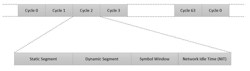
The Communication Cycle is the fundamental time unit of the FlexRay protocol, defining how and when ECUs in a cluster exchange data. It repeats at fixed intervals and determines the rate of communication (baud rate) across the network.
For example, if the cycle time is set to 5 milliseconds, each ECU gets a chance to transmit data every 5 ms. This structured and repetitive approach enables both deterministic (timing-guaranteed) and flexible communication.
A complete communication cycle is divided into four segments: the Static Segment for time-critical messages, the Dynamic Segment for event-driven communication, the Symbol Window for network management tasks and the Network Idle Time (NIT) for clock synchronization and fault recovery.
Static Segment
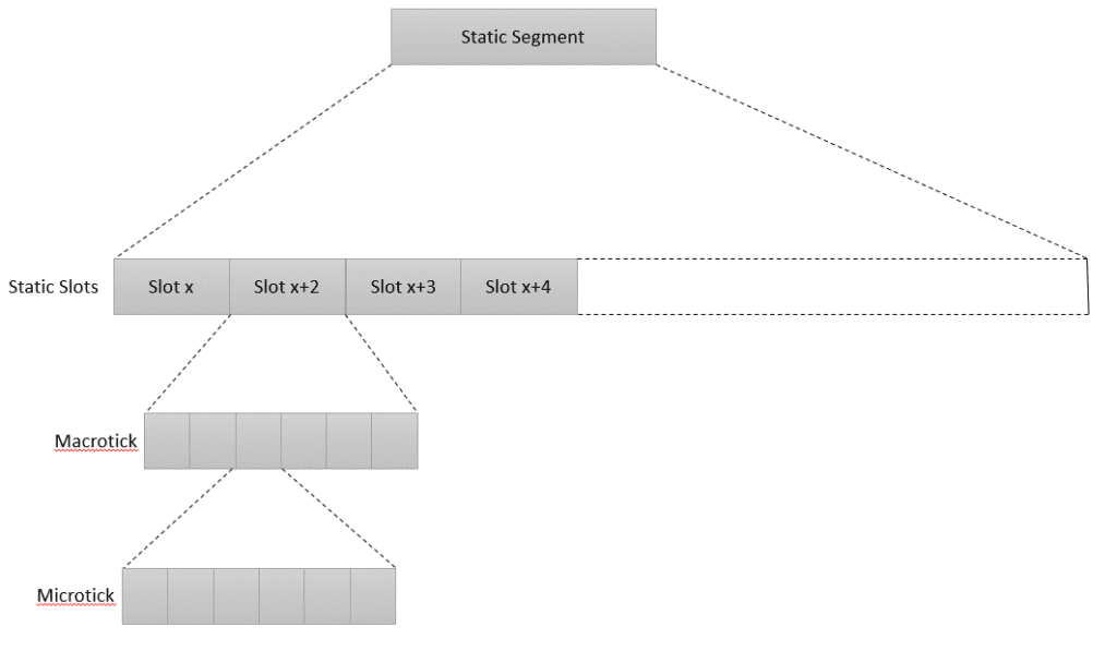
The Static Segment is a time-triggered and mandatory portion of the FlexRay communication cycle in which access to the bus is strictly controlled by time. It consists of fixed-length time slots, known as Static Slots, which are pre-assigned to specific nodes (ECUs).
Each node is allowed to transmit during its allocated slot, regardless of whether it has data to send or not. This ensures deterministic communication with guaranteed latency and minimal jitter, which is essential for safety-critical functions, such as sensor data transmission in ADAS.
The number of Static Slots in a Static Segment is fixed and a frame is transmitted only if its Frame ID matches the corresponding Slot ID. The duration of each Static Slot is defined in macroticks, which are standardized units of time used across the entire FlexRay cluster for synchronization.
A macrotick is derived from a smaller unit called a microtick, which originates from the local oscillator of each communication controller. While microticks are node-specific, macroticks ensure cluster-wide time consistency, forming the foundation for FlexRay’s precise timing structure.
Dynamic Segment
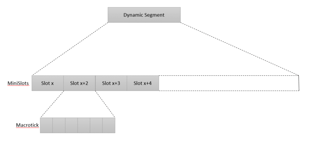
The Dynamic Segment is an optional, event-triggered portion of the FlexRay communication cycle that provides flexibility for transmitting non-time-critical data. Unlike the Static Segment, where time slots are fixed, the Dynamic Segment uses a mini-slotting scheme based on Flexible Time Division Multiple Access (FTDMA).
In this approach, nodes are allocated Minislots, which are the smallest time units within the segment. If a node has data to transmit and wins arbitration (based on frame ID priority), it can begin transmission during its assigned Minislot.
If the data exceeds the duration of one Minislot, the node can extend its use into subsequent slots, allowing variable-length transmission. This makes the Dynamic Segment ideal for transmitting data that doesn’t require strict timing, such as messages from infotainment systems or diagnostic tools.
Each Minislot is a multiple of macroticks, which in turn are derived from microticks i.e. the smallest unit of time defined by the node’s local oscillator, ensuring the timing remains consistent across the FlexRay network.
Symbol Window
The Symbol Window is an optional, time-fixed segment in the FlexRay communication cycle, primarily used for network management and coordination tasks. During this window, a single symbol can be transmitted to perform functions such as synchronization, signaling or wake-up commands.
It plays a key role in maintaining network stability, especially during startup or when recovering from errors. The duration of the Symbol Window is globally defined and expressed in macroticks, which are derived from microticks, ensuring accurate timing across the FlexRay cluster.
Although no application data is transmitted during this period, the Symbol Window supports critical control communication within the network.
Network Idle Time (NIT)
NIT is a mandatory segment in the FlexRay communication cycle that serves as a gap between two consecutive cycles. Its primary function is to allow all nodes in the cluster to perform clock correction and re-synchronize to the global time base.
This period is crucial for maintaining timing accuracy and network integrity, especially in systems that rely on precise coordination between ECUs. Additionally, NIT provides a buffer for fault recovery and helps ensure that all nodes are aligned before the next communication cycle begins.
The duration of NIT is defined in macroticks, which are derived from microticks, ensuring consistent and synchronized timing across the entire network.
Frame Structure of FlexRay protocol
The Frame Structure of FlexRay is designed to ensure efficient and reliable data transmission across the network. It includes a Frame Header that contains control information such as the frame identifier and payload length, crucial for proper message handling.
The Payload Segment follows, carrying the actual data to be transmitted, and its length can vary based on application requirements. A CRC (Cyclic Redundancy Check) is appended to the frame for error detection, allowing receiving nodes to verify the integrity of the transmitted data. FlexRay frames consist of several fields, each serving a specific purpose in ensuring reliable communication:
Frame Header of FlexRay
Contains control information, such as the frame identifier, payload length, and cycle count.
Payload Segment
Holds the actual data being transmitted. The length of the payload can vary depending on the application requirements.
CRC (Cyclic Redundancy Check)
Provides error detection by appending a CRC code, allowing the receiving node to verify the integrity of the data.
Synchronization in FlexRay protocol
Synchronization is crucial in FlexRay to maintain deterministic communication. It ensures that all nodes on the network operate in harmony by aligning their local clocks to a global time base. This is achieved through periodic synchronization frames exchanged between nodes, allowing them to adjust their clocks and maintain a unified schedule.
The process guarantees that data transmission occurs precisely within the designated time slots, adhering to the deterministic nature of the protocol. Effective synchronization is crucial for maintaining consistent and reliable communication, particularly in safety-critical automotive applications.
Fault Tolerance in FlexRay protocol
Fault Tolerance in FlexRay is achieved through several key mechanisms designed to maintain network reliability and robustness. FlexRay enhances fault tolerance through several mechanisms:
Dual-Channel FlexRay Architecture
The Dual-Channel Architecture in FlexRay enhances network reliability and fault tolerance by utilizing two independent communication channels (Channel A and Channel B). These channels operate in parallel, allowing data to be transmitted simultaneously over both, which provides redundancy in case one channel fails.
If a fault occurs in one channel, the system can switch to the other channel to maintain uninterrupted communication. This design not only improves fault tolerance but also enhances overall network robustness and data integrity.
Bus Guardian
The Bus Guardian is a critical component responsible for ensuring that each node adheres to the network’s communication schedule and rules. It monitors the bus for any deviations or unauthorized transmissions, preventing nodes from sending data outside their allocated time slots.
This mechanism helps maintain the deterministic nature of the network and avoids collisions and disruptions. Additionally, the Bus Guardian prevents faulty nodes from disrupting the network by enforcing communication rules and schedules.
Error Detection and Correction
Error Detection uses Cyclic Redundancy Check (CRC) to detect errors in transmitted data by appending a CRC code that is verified upon reception. If discrepancies are found, the system can trigger error recovery procedures to correct or re-transmit the faulty data.
This robust error management ensures reliable communication and helps maintain the network’s stability, even in the presence of transmission errors.
Future of FlexRay
The future of FlexRay is shaped by its continued relevance in existing automotive systems and its integration with newer technologies like Automotive Ethernet. As vehicles increasingly adopt centralized and distributed control architectures, FlexRay will play a key role in ensuring reliable communication between control units. Advances in fault tolerance and reliability will further enhance the protocol’s robustness, addressing the growing complexity of automotive systems.
Additionally, FlexRay is poised to support emerging applications in electric and autonomous vehicles, where its high data rates and deterministic communication are crucial. Industry support and ongoing standardization efforts will drive the evolution of FlexRay, ensuring it meets future automotive requirements.
Its adaptability and integration with new technologies will secure its place in the evolving automotive landscape.
Final Thoughts
FlexRay is a robust and reliable communication protocol designed to meet the stringent demands of modern automotive systems. Its deterministic nature, high data rates, and fault tolerance make it ideal for safety-critical applications and real-time control systems.
Understanding FlexRay’s architecture, communication cycle, and advantages is essential for developing and implementing advanced automotive technologies. As the automotive industry continues to innovate, FlexRay will remain a vital component in ensuring efficient and reliable vehicle communication.
