
SAE J1939 is a high-layer protocol based on the CAN network. It is used in trucks, buses, earth moving machines and heavy-duty vehicles for in-vehicle networking and diagnostics. SAE J1939 is also used in agriculture and forestry machinery (ISO 11783), military vehicles (MiL CAN), ships, rail vehicles, and marine navigation systems (NMEA 2000).
Table of Contents
History of SAE J1939
The development of SAE J1939 began in the late 1980s aiming to create a communication protocol for heavy-duty vehicles. In 1988, initial development of SAE J1939 protocol started. By the year 1994 first official release of SAE J1939 standard was released.
In 2000s decade, SAE J1939 was integrated with other protocols and its functionalities were expanded. By 2010s, SAE J1939 was adopted for a broader range of industries and vehicles like Agriculture, Military, rail and marine.

What is SAE J1939 protocol?
SAE J1939 is a set of standards defined by the Society of Automotive Engineers (SAE) for communication and diagnostics among vehicle components. This protocol is based on the CAN protocol. SAE J1939 does not support master / slave or client / master architecture. SAE J1939 uses 29 bit CAN identifier for message frames and 250 kbit/second (some running at 500 kbit/sec) baud rate.
Network management defined in SAE J1939/81 allows a maximum of 30 notes in a network. SAE J1939 messages use the CAN 2.0B physical layer. It allows 11 bit CAN messages to be sent as proprietary messages on bus. Before transmitting messages on bus, each node must claim a one byte network address. Maximum bus length is 40 m and maximum note count is 30. SAE J1939 consists of a shielded twisted pair of wires and the shield is connected directly to the ground.

There are three different types of SAE J1939 communication i.e. Destination specific (peer-to-peer), Broadcast and Proprietary. SAE J1939 protocol is mainly used in heavy duty vehicles, like trucks, buses, excavators, diggers, cranes, ships, rails, military vehicles etc.
The SAE J1939 protocol helps in logging data, diagnosing the vehicle, identifying errors, and logging DTCs. A Vehicle DTC is a standardized code that identifies specific issues within a vehicle’s systems, allowing mechanics to diagnose and repair faults efficiently. For all truck manufacturers DTCs are essential for detecting faults.
For example, Volvo truck Fault Codes DTC list provides a huge list of error codes with explanation. This detailed insight helps to maintain optimal performance and address potential malfunctions quickly.
SAE J1939 message frame format
SAE J1939 messages are structured in a specific format to ensure compatibility and interoperability with different types of vehicles. Lets understand the CAN frame format for SAE J1939 protocol:
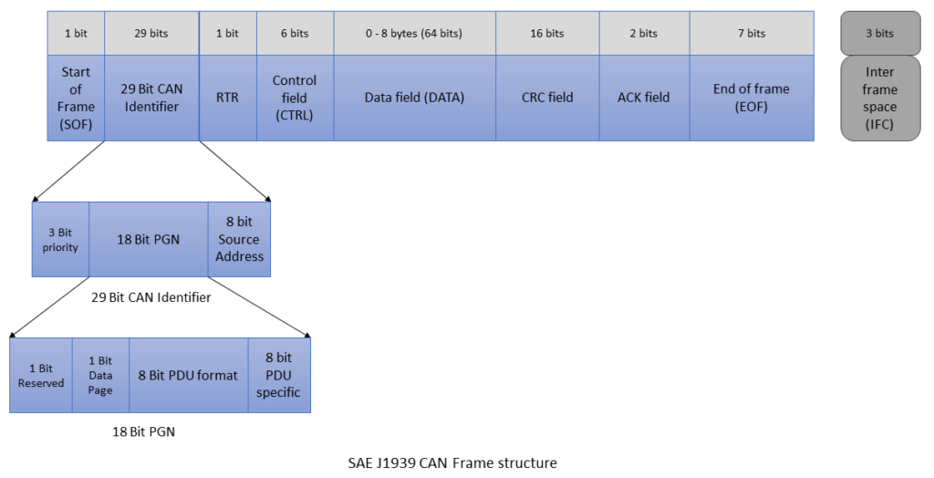
Priority field
It is of 3 bits. i.e. 2^3 = 2x2x2 = 8 different values. ‘000’ is the highest priority and ‘111’ is the lowest priority. High priority data messages are assigned to time critical data such as torque, control data from transmission to engine. Whereas, low priority messages are assigned for non critical data such as engine configuration data.
Parameter Group Number (PGN)
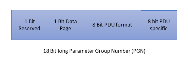
PGN stands for Parameter Group Number and identifies the parameter group (PG). It is 18 bits long. Parameter Groups point to the information of parameter assignment within 8 bytes of CAN data field, repetition rate and priority. There are 8672 different Parameter Groups per page and 2 pages are available.
Source Address
It is 8 bits long i.e. 2^8 = 256 different addresses available. These are the last 8 bits of a 29 bit CAN identifier value. Source address means it is the address of the transmitting (Tx) ECU.
Reserved
This field is reserved for future purposes and is one bit long. It should always be set to ‘0’ for J1939 when transmitting messages.
Data Page
It is 1 bit long and identifies the page (0 or 1) that a message belongs to. It is a page selector for the PDU (Protocol Data Unit) format field. Currently it is set at 0 and 1 (i.e. Page 1) is reserved for future use. 0 value means it points to page 0. Data page is used to increase the number of available PGNs. Most of the PGNs are on page 0.
PDU Format
It is 8 bits long i.e. 2^8 = 256 different values (0 – 255).
PDU format values 0 – 239 (i.e. PDU 1) are destination specific. PDU1 indicates a destination address in the PDU Specific field.
PDU format values 240 – 255 (i.e. PDU 2) are Broadcast. PDU 2 indicates an extension to PDU format. It is used for data that is meant to be broadcast on a regular and defined interval.
PDU Specific
It is 8 bits long. Its content is interpreted according to information in the PDU format field.
Example of PGN
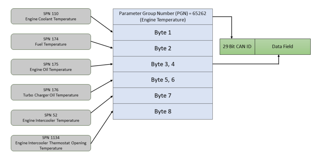
Lets take an example: PGN 65262 (0xFEEE)
Priority = 6
Reserved = 0
Data Page = 0
PDU Format = 254
PDU Specific = 238
NOTE: PGN’s least significant byte is always 0x00 for PDU 1 i.e. PGN of 0xEF01 would never be a valid PDU1.
PGN Range
| Data Page | PGN Range (hex) | Number of PGNs | SAE or Manufacturer assigned | Communication |
|---|---|---|---|---|
| 0 | 0x000000 – 0x00EE00 | 239 | SAE | PDU1 = Peer to Peer |
| 0 | 0x00EF00 | 1 | Manufacturer | PDU1 |
| 0 | 0x00F000 – 0x00FEFF | 3840 | SAE | PDU2 = Broadcast |
| 0 | 0x00FF00 – 0x00FFFF | 256 | Manufacturer | PDU2 |
| 1 | 0x010000 – 0x01EE00 | 239 | SAE | PDU1 |
| 1 | 0x01EF00 | 1 | Manufacturer | PDU1 |
| 1 | 0x01F000 – 0x01FEFF | 3840 | SAE | PDU2 |
| 1 | 0x01FF00 – 0x01FFFF | 256 | Manufacturer | PDU2 |
SAE = Assigned by Society of Automotive Engineers
Manufacturer = Manufacturer specific i.e. proprietary messages
Broadcast Announce Message (BAM)
In order to broadcast a multi-package message a node must first send a Broadcast Announce Message (BAM). A BAM contains following contents:
- PGN of the multi-package message
- Size of the multi-package message
- Number of packages
BAM is embedded in the Transport Protocol – Connection Management (TP.CM) PGN 60416 and the actual data transfer is handled by using Data transfer PGN 60160.
NAME (64 bits)
SAE J1939 defines a 64-bit NAME to uniquely identify each ECU. Each ECU must hold at least one NAME and one address for identification purposes. The ECU address defines the source or destination for messages, while the ECU NAME indicates the main function performed at that address. Additionally, a function instance indicator is used when multiple ECUs with the same main function share the same network.
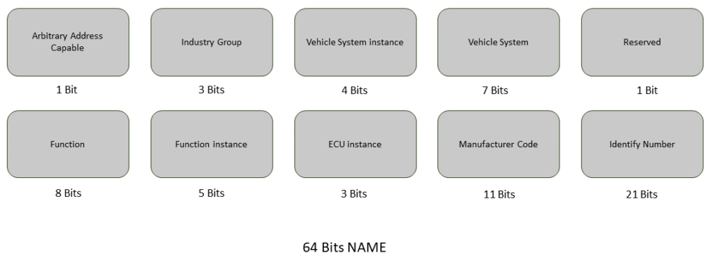
1 + 3 + 4 + 7 + 1 + 8 + 5 + 3 + 11 + 21 = 64 Bits NAME.
Each ECU utilizes an 8 bit address to identify the source of a message or to access (destination address) another ECU in the network.
Address Claim Procedure
The Address Claim Procedure is designed to assign addresses to ECUs immediately after network startup, ensuring that each assigned address is unique to the ECU. The SAE J1939 standard defines Preferred Addresses for commonly used devices to minimize the likelihood of multiple devices requesting the same address.
Two possible Address Claiming scenarios:
- Sending an Address Claimed Message (standard):
- ECU sends address claimed message on the CAN bus.
- ECUs receiving address claim will record and verify claimed address with internal address table.
- In case of address conflict, ECU with the lowest NAME value will succeed.
- Remaining ECUs must claim different addresses or stop transmitting to the network.
- Request for Address Claimed Message:
- Necessary procedure for ECUs powering up late (example trailers, diagnostic tools etc)
- Used to determine and claim available addresses or to find out which ECUs are currently on the network.
Final Thoughts
SAE J1939 is a critical protocol in the automotive and heavy-duty vehicle industries, providing a standardized and reliable communication framework. Its widespread adoption and continuous evolution make it a cornerstone for vehicle networking, ensuring interoperability and efficient operation across various applications.
By understanding the intricacies of SAE J1939, automotive professionals can leverage its capabilities to develop advanced and robust vehicle systems, paving the way for future innovations in the industry.
SAE J1939 is widely used in the commercial vehicle industry due to its robustness, reliability, and widespread adoption by vehicle manufacturers and suppliers. It enables seamless communication between various ECUs, allowing for efficient coordination of vehicle systems & the implementation of advanced functionalities such as engine control, transmission management, brake systems, and more.
The standardization of SAE J1939 facilitates interoperability and compatibility between different vehicle components and systems, making it an essential part of the modern commercial vehicle electronic architecture.
