
UDS is a vehicle diagnostics protocol used in the automotive industry for communication between a tester and ECUs. It is specified in the ISO 14229-1 standard. UDS supports a wide range of diagnostic services such as reading and clearing fault codes, ECU programming, and sensor data monitoring. It enables precise control and monitoring of vehicle subsystems, making it essential for both development and after-sales diagnostic operations.
Table of Contents
What is the UDS protocol (ISO 14229)?
UDS stands for Unified Diagnostic Services, and it is a vehicle Diagnostic communication protocol. It is used in automotive electronics for the diagnostic communication between a tester device (scanner tool, Diagnostic software, datalogger etc) and ECUs.
It is based on the ISO 14229-1 standard and uses the ISO 15765-2, also known as CAN-TP (transport protocol), to send and receive messages over the CAN bus.
UDS communication works on a client (Tester) – Server (ECU) relationship where the client requests diagnostic information from the server, and the server responds. UDS diagnostics protocol enables:
- Reading and clearing diagnostic trouble codes (DTC) saved in the vehicle.
- Extracting important values from the vehicle like Engine Coolant temperature, state of charge (SoC), VIN, etc.
- Unlocking vehicle using Seed-Key algorithm to gain access to various parameters within ECU memory.
- Firmware flashing, modifying ECU behaviour via resets, etc.
- Upload and download vehicle data parameters.
UDS protocol on OSI Network Layer
UDS operates on the application layer (layer 7) and session layer (layer 5) of the OSI model. The application layer handles the actual diagnostic services, such as reading and writing data from ECUs, performing diagnostic routines, and managing diagnostic sessions.
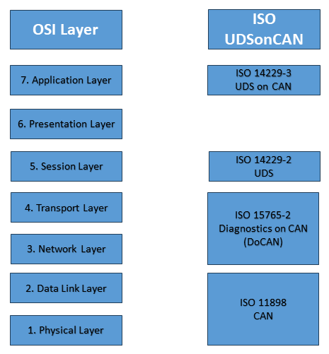
Session layer manages the establishment, maintenance, and termination of diagnostic sessions between the diagnostic tool and the ECU. It ensures reliable communication and data transfer.
One challenge when implementing Diagnostics on CAN is the payload limit of CAN, which is 8 bytes per CAN frame. Vehicle Diagnostics data is often larger than 8 bytes. In this case, data segmentation is required, where more than 8 bytes of diagnostic data is divided into multiple frames. Data segmentation is achieved using ISO 15765-2, also known as CAN-TP or DoCAN.
Also, UDS used either Physical or functional addressing scheme to address ECUs and tester device.
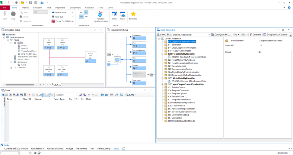
Tester tools (like VSpy, CANoe) provide inbuilt support for UDS services and a graphical way to connect to the ECUs.
Structure of UDS Message Frame or UDS PDU (Protocol Data Unit)
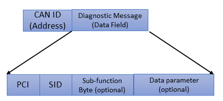
The UDS PDU (Protocol Data Unit) or UDS message consists of the following:
- CAN-ID, i.e. CAN-Address
- Diagnostic Message (Data field)
- PCI Byte
- Service Identifier (SID)
- Sub-function byte (optional)
- Data parameter (optional)
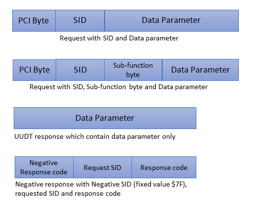
Types of UDS messages
Different types of UDS messages (PDUs) are described below:
1. Request Frame
A message sent from a Tester device to an ECU requesting diagnostic data is called a Diagnostic Request frame. It is further categorized into two types:
a) Request with SID and Data parameter
This request contains a Service Identifier (SID) and data parameters. SID defines the requested Diagnostic service. Data parameters further contain the required information like DID (Data Identifier) information.
b) Request with SID, Sub-function byte and Data parameter
This request contains a Sub-function byte as well. Sub-function byte is like a sub-category of Service Identifier (SID).
2. Response Frame
A message sent from an ECU to a Tester device with diagnostic data is called a Diagnostic Response frame. This message is sent in response of a Diagnostic request message. It is further categorized into three types:
a) Positive response with PCI byte, Response SID, Sub-Function ID and Data parameter
This diagnostic frame contains a positive response to the request message.
b) UUDT response (which only contains data parameters)
A diagnostic response which only contains the data i.e. no response SID or sub-function byte is mentioned in the response. Its just the data.
c) Negative response with negative SID (Fixed value $7F), repeated requested SID and response code
This message contains a negative response to the requested diagnostic service along with the reason for the negative response.
Explaining different fields in a Diagnostic message
A Diagnostic message comprises of different fields. Now, we will discuss these fields in detail:
Protocol Control Information (PCI) Byte
The PCI byte is a fundamental part of the UDS message structure. It resides in the header of UDS messages and plays a crucial role in determining the type and purpose of the message being transmitted.
Depending on the frame type (first frame, Single frame, Consecutive frame and Flow control), the value of PCI bytes ranges between values 1, 2 and 3.
Service Identifier (SID)
The SID serves as an identifier for the specific diagnostic service being requested or responded to. It indicates the type of action that a diagnostic tool wants the ECU to perform.
Each diagnostic service in the UDS protocol and SAE J1979 OBD-II protocol is assigned a unique SID, ensuring standardized communication across different vehicle makes and models. Different SID ranges are assigned to different diagnostic protocols.
Sub-Function byte
It is defined for request SID only. It allows detailed parameterization of the service. However, not all UDS services require a Sub-function byte. Therefore, it’s an optional field. Sub-function byte reduces the available space for additional data parameters in CAN single frame to 5 bytes (for normal addressing).
However, the reduction of available space is not of great importance because it affects only the diagnostic request. And requests are usually shorter than the diagnostic responses.
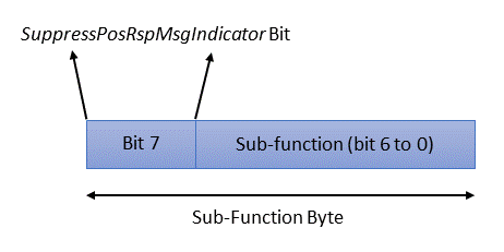
The most Significant Bit (MSB), i.e. bit 7 of the sub-function byte, is the SuppressPosRspMsgIndicator Bit. If it is 1, then the Tester does not require a response message.
Bit 6 to 0 -> A total of 7 bits to specify Sub-function. This means 128 (2^7) different Sub-function values.
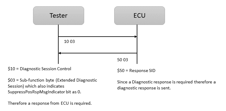
Example: Tester sends a Diagnostic message with $10 (Diagnostic Session Control) UDS service and $03 as a Sub-function byte. $03 indicates that the SuppressPosRspMsgIndicator bit (7) is 0, which means the Tester requires a diagnostic response, and ECU sends a 50 03 diagnostic response.
Response Code
There are three categories of UDS response codes:
- Category 1 (Value $00): Only one value ($00) is used internally in the ECU for positive response and does not appear on the diagnostic bus.
- Category 2 (Value $01 to $7F): Contains the established values to report communication errors.
- Category 3 (Value $80 to $FF): This category serves the exact specification of errors that in the past were reported by the “collective code” $22 (conditions not correct). UDS standards now occupy values of $90 to $FE and are no longer available for vehicle manufacturers and suppliers.
Data Parameters
Different types of request data parameters are used in many UDS request services to provide further information. Example: Service $22 (Read Data by Identifier). Here, the $22 service uses a Data Identifier (DID) to read the value of that DID. It is a 2-byte value between 0 and 65535 (0xFFFF).
Positive vs. Negative UDS diagnostic responses
Positive UDS response refers to a successful or valid response from the ECU to a diagnostic request. For example, a positive response to the ReadDataByIdentifier ($22) request will contain the response SID 0x62 ($22 + $40), the 2-byte Data Identifier (DID), and finally, the actual requested DID data.
A negative UDS response is an unsuccessful or invalid response from the ECU to a diagnostic request. It could be due to various reasons like service is not supported, communication errors, unsupported requests, or faults within the ECU itself. Negative responses can hinder diagnostic procedures and may require further investigation to determine the cause of the failure.

Example of Positive Response UDS Communication
Tester Sends a [2A 03 0C 0D] request to Read Data by Periodic Identifier ($2A) with sub-function byte as Transmission Mode set as ‘SendAtFastRate’ ($03). Next is Data parameters, i.e. Data Identifier (DID) $0C, which is Engine RPM, and DID $0D, which is vehicle speed.
Now, ECU responds with response SID $6A ($2A + $40).
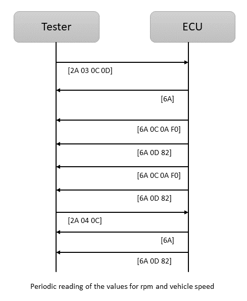
ReadDataByPeriodicIdentifier requests the periodic transmission of data record values at a transmission rate defined by sub-function byte.
The next frame is [6A 0C 0A F0], which means ECU sends the rpm $0C value (0A F0). 0A F0 (hexadecimal value) is equivalent to 2800 rpm (decimal value).
Following frame is [6A 0D 82], which means the vehicle speed $0D is 130 km/h ($82).
[6A 0C 0A F0] is received again, meaning the rpm is 2800 rpm. The next frame is [6A 0D 82] again, meaning the vehicle speed is 130 km/h.
Now, TesterTester a [2A 04 0C] request where sub-function $04 means Transmission mode is set to ‘StopSending’ for rpm. Therefore, only vehicle speed data will be sent.
The next frame is [6A 0D 82], which means the vehicle speed $0D is 130 km/h ($82).
Finally, send a [2A 04 0D] to stop transmission of vehicle speed or send a [2A 04], which will stop both rpm and vehicle speed.
Example of Negative Response UDS Communication
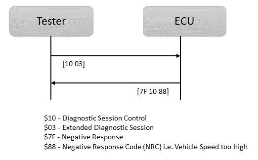
Tester Sends a [10 03] request to enter in Diagnostic Session control ($10) with sub-function byte as Extended Diagnostic session ($03).
Now, due to the vehicle speed being too high, ECU sends a Negative response (Fixed value $7F), followed by response SID ($10) and NRC ($88).
List of UDS protocol Services
Below is the list of UDS services available for diagnostic communication between tester and ECUs:
| SID | Diagnostic Service Type | Diagnostic Service |
|---|---|---|
| $10 | Diagnostic and Communication Management | Diagnostic Session Control |
| $11 | Diagnostic and Communication Management | ECU Reset |
| $27 | Diagnostic and Communication Management | Security Access |
| $28 | Diagnostic and Communication Management | Communication Control |
| $3E | Diagnostic and Communication Management | Tester Present |
| $83 | Diagnostic and Communication Management | Access Timing Parameter |
| $84 | Diagnostic and Communication Management | Secured Data Transmission |
| $85 | Diagnostic and Communication Management | Control DTC Setting |
| $86 | Diagnostic and Communication Management | Response On Event |
| $87 | Diagnostic and Communication Management | Link Control |
| $22 | Data Transmission | Read Data by Identifier |
| $23 | Data Transmission | Read Memory by Address |
| $24 | Data Transmission | Read Scaling Data by Identifier |
| $2A | Data Transmission | Read Data by Periodic Identifier |
| $2C | Data Transmission | Dynamically Define Data Identifier |
| $2E | Data Transmission | Write Data by Identifier |
| $3D | Data Transmission | Write Memory by Address |
| $14 | Stored Data Transmission | Clear Diagnostic Information |
| $19 | Stored Data Transmission | Read DTC Information |
| $2F | Input and Output Control | Input output Control by Identifier |
| $31 | Remote Activation of Routine | Routine Control |
| $34 | Upload and Download | Request Download |
| $35 | Upload and Download | Request Upload |
| $36 | Upload and Download | Transfer Data |
| $37 | Upload and Download | Request Transfer Exit |
Key Features of UDS protocol
Key features and aspects of UDS protocol include:
- Standardized Protocol: UDS provides a standardized and uniform way of communicating with ECUs across different vehicle manufacturers. This standardization allows diagnostic tools from various manufacturers to interact with ECUs consistently.
- Wide Adoption: UDS is widely used in modern vehicles, and it has become the primary diagnostic protocol in most of the automotive applications.
- Diagnostic Services: UDS defines a set of diagnostic services that allow diagnostic testers to read and clear DTCs, request sensor data, perform tests, program ECUs, and carry out other diagnostic-related tasks.
- Transport Protocols: UDS can operate over various transport protocols, including CAN, FlexRay, Ethernet, and others. This flexibility allows UDS to be used in different network configurations.
- Session and Security Levels: UDS supports multiple diagnostic sessions and security levels, which help control access to specific diagnostic functions and protect against unauthorized access to sensitive vehicle data and functionalities.
- Data Exchange Format: UDS defines a structured data exchange format (ODX) for diagnostic requests and responses, allowing diagnostic tools and ECUs to interpret and process information accurately.
- Error Handling: UDS includes error handling mechanisms to ensure reliable communication between the diagnostic Testers and ECUs, even in the presence of network or communication errors.
- Complements OBD-II: While UDS is part of the broader OBD standards, it complements the OBD-II (On-Board Diagnostics II) standard and provides more advanced and standardized diagnostic capabilities beyond the basic emissions-related diagnostics offered by OBD-II.
Final Thoughts
UDS is essential for vehicle diagnostics, maintenance, and repair, as it allows service technicians and engineers to access and interact with the vehicle’s ECUs effectively. Diagnostic tools supporting UDS can retrieve valuable information about the vehicle’s systems, identify faults, perform tests, and reprogram ECUs as needed, contributing to efficient and accurate vehicle servicing.
As vehicles become increasingly complex and software-driven, UDS remains a foundational protocol that supports evolving diagnostic requirements. Its widespread adoption across OEMs ensures interoperability and consistency in diagnostic procedures across different vehicle platforms.
