
ISO 15765-2 is an international standard protocol that specifies the diagnostic communication over CAN network. It defines the process of sending more than 8-bytes of data over CAN Diagnostic frames.
This protocol ensures reliable segmentation and reassembly of large diagnostic messages, which is essential for comprehensive ECU communication. It plays a key role in enabling UDS over CAN, making it fundamental for in-vehicle diagnostics.
Table of Contents
Introduction
A single CAN frame allows sending only 8 bytes of data. However, during Vehicle Diagnostics there might be a few cases when the Diagnostic response from the ECU contains more than 8 bytes of data. In such cases ISO 15765-2 or CAN-TP (CAN Transport Protocol) or DoCAN (Diagnostics over CAN) Protocol comes into effect.
ISO 15765-2 defines a transmission method that allows sending up to 4096 bytes (2^12) of data via CAN bus which is not possible in normal CAN messages (onboard communication). For this purpose, the CAN data is divided / segmented into different CAN frames.
The actual data sent via a single Diagnostic CAN frame is still 8 bytes. However, those multiple 8 byte frames are sent in a defined manner so that the tester can interpret the long Diagnostic data.
Addressing modes in ISO 15765-2 protocol
There are 2 types of addressing modes used in ISO 15765-2 or CAN-TP to identify the source and destination of messages:
Normal Addressing
The deployment of CAN messages with a 11-bit identifier for diagnostics communication is called Normal Addressing. The advantages of this type of addressing is that full 8 bytes (1 byte as PCI byte and 7 bytes as Diagnostic data) of the CAN frame can be sent as data.
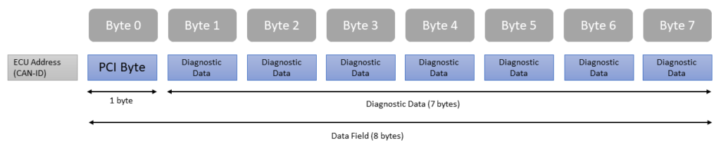
Here, a maximum of 7 bytes are left for the diagnostic data. If the diagnostic message is longer than 7 bytes, then USDT/UUDT data segmentation is required.
Extended Addressing (Mixed Addressing)
When Addressing gets more complex (example in case of Gateway ECUs), the mechanism of Extended Addressing can be used. 11-bit diagnostic CAN identifier is extended by the first byte of the CAN data field. Due to the fact that the CAN-ID and a part of the data field are now used for addressing, this addressing scheme is also called Mixed Addressing.
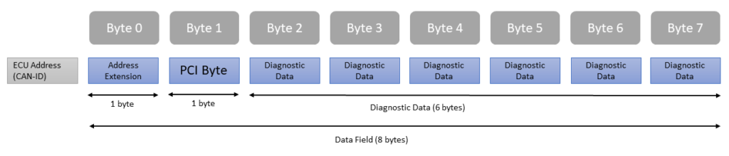
Advantage of Extended Addressing is that a bigger address space is available, or 256 different ECUs can be addressed by one request CAN-ID. However, the space for diagnostic messages is reduced to 6 bytes.
The virtue of Mixed Addressing is that the addressing method can become more complex. And, due to the reduction of available space for the service in the data field and for the diagnostic data, data segmentation is probably needed more often with Extended Addressing.
Different Types of Frames in ISO 15765-2 protocol
As mentioned, in case of Diagnostic data more than 8 bytes, CAN data is segmented into different CAN frames. But, how does this data segmentation work? For this purpose ISO 15765-2 or DoCAN has 4 types of frames with 2 major categories:
- Single Frame ($0)
- Multi-Frame
- First Frame ($1)
- Consecutive Frame ($2)
- Flow Control Frame ($3)
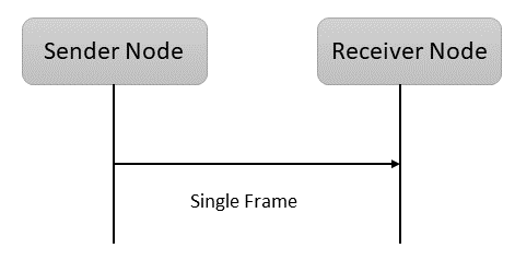
1. Single Frame
When a single CAN frame is sufficient to send the entire diagnostic data then a single frame is used to transmit the diagnostic data. It contains 1 PCI (Protocol Control Information) byte. Here a maximum of 7 bytes of diagnostic data can be sent.
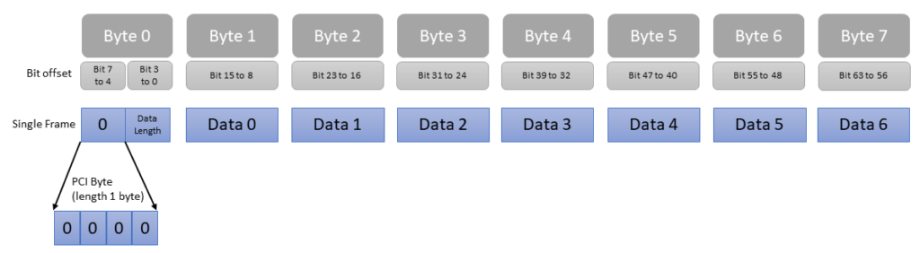
Single Frames are the simplest and most efficient way to transfer diagnostic data in DoCAN, as they require only one message to be sent. They do not require any flow control mechanisms or additional message framing.
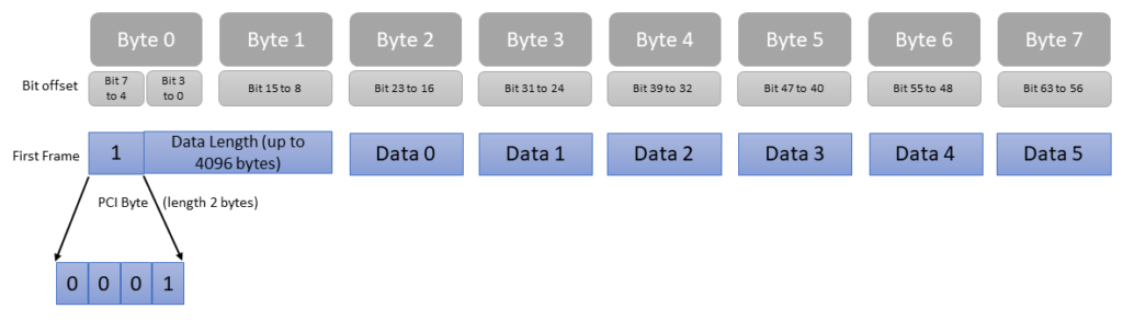
2. First Frame
If the diagnostic data can not fit in a single CAN frame, it is then divided into several smaller frames and a combination of multiple frames (First frame, Flow Control and Consecutive frame) is required. It starts with a First frame which is sent by the ECU to the tester.
First frame contains 2 PCI bytes and the first part of the diagnostic response which can be of maximum 6 bytes. The First Frame initiates this process and contains important information like the total length of the diagnostic data.
3. Flow Control Frame
Flow control is sent by the tester to the ECU and is used to manage the flow of data between the transmitter (ECU) and the receiver (tester). It includes information such as the flow status, block size and minimum separation time. It contains 3 PCI bytes. Tester confirms the receipt of the First frame by sending a Flow control back to the ECU.
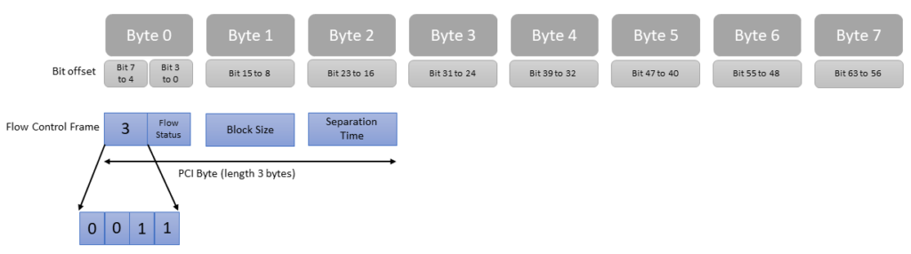
It tells about the capabilities of the tester, like the number of consecutive frames that an ECU can transmit before the tester sends an acknowledgement message. Tester controls the data segmentation by using Flow control frame.
a) Flow Status
It indicates whether the ECU can proceed with the message transmission. Here are the Flow Status values:
| Value | Mnemonic | Description |
|---|---|---|
| $0 | CTS | Continue to send |
| $1 | WT | Wait |
| $2 | OVFLW | Overflow |
| $3 – $F | Reserved |
b) Block Size
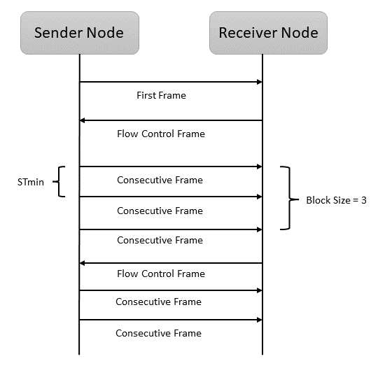
It defines the maximum number of consecutive frames a ECU can send before it has to wait for another Flow Control frame from Tester. Except for the last block, the number of transmitted consecutive frames and the value of the block size are the same.
Also with the exception of the last consecutive frame (which is adjusted to the length of the remaining data), the data field of a consecutive frame always remains 8 bytes of data.
Example: If Block size is 0, then Consecutive Frame is transmitted by ECU without waiting for the Flow Control. Block size between 1-255 defines how many Consecutive Frames can be sent before ECU waits for another Flow Control from Tester.
c) Parameter Separation Time (STmin)
It is the minimum time slot between two consecutive frames. Example: If STmin is between 0 – 127 ($7F) then separation time is 0 – 127 ms (millisecond). For $F1 it’s 100 μs (microsecond). For $F9 it’s 900 μs.
NOTE: Block Size should be more, and STmin should be less for a faster data transfer.
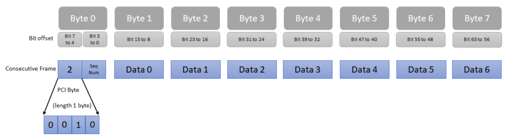
4. Consecutive Frame
Consecutive Frame is used to transmit the data in consecutive segments. It is sent from ECU to the tester. Each Consecutive Frame contains a segment of the remaining diagnostic data, as well as a sequence number that identifies the position of the segment. It contains 1 PCI byte.
Example of Data Segmentation in a Diagnostic response using ISO 15765-2 protocol
Tester sends a CAN Diagnostic Request (01 03) to both ECM and TCM.
01 03 -> Here, $0 in the first byte represents Single Frame. Following $1 represent data length (i.e. 1 byte of data).
Now $03 is the 1 byte data. Here $03 is a Service Identifier (SID) which is OBD-II SAE J1979 service Request EmissionRelatedDiagnosticTroubleCodes (also known as Mode 3).
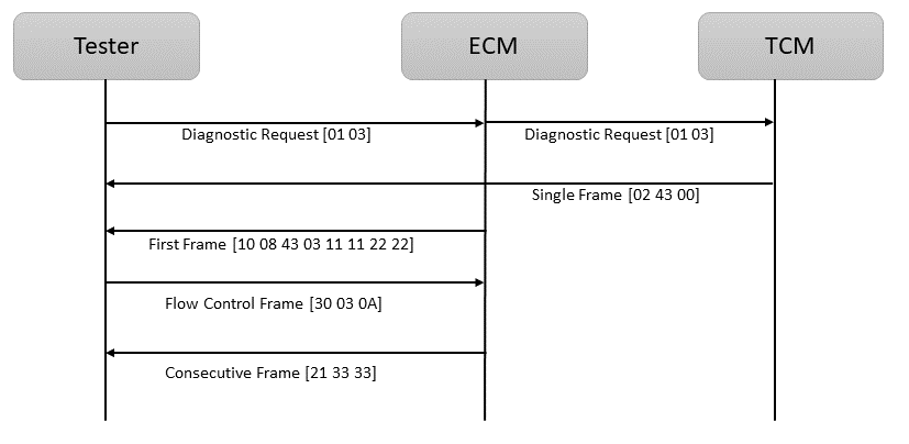
TCM responds with a single Frame (02 43 00). $0 represents Single Frame, $2 represents 2 bytes of data which is 43 00. Now, $43 is the response Service Identifier for the request service ($03) and $00 means no DTCs. Since there are no DTCs in TCM, entire diagnostic data fits in a single frame and here a single frame is sent by TCM.
ECM responds with a First Frame (10 08 43 03 11 11 22 22). First and second data bytes are 10 08 where $1 stands for First frame, and $0+$08 (second nibble of first byte and entire second byte) stands for 8 bytes of data. As this will not fit in a single CAN frame, therefore a First frame is sent and the remaining data will be sent in Consecutive frames.
Third byte ($43) is the response Service Identifier for the request service ($03). Fourth byte ($03) means there are a total of 3 DTCs. The next four data bytes contain the DTC information. 11 11 is 1st DTC and 22 22 is 2nd DTC. 3rd DTC information is pending and will be sent in Consecutive frame.
Now a Flow Control frame (30 03 0A) is sent by the Tester. $3 stands for Flow Control and $0 stands for Flow Status which means ‘Continue to Send’. $03 in the second byte is the Block Size which means ECU can send 3 consecutive frames without the need of any new Flow Control. And finally, $0A in the third byte means separation time (STmin) is 10 ms.
After this, ECU sends the remaining data in the Consecutive frame which is 21 33 33. $2 stands for Consecutive frame. $1 is the sequence number meaning that this is the first Consecutive frame. Finally, 33 33 is the 3rd DTC.
Now, 10 08 43 03 11 11 22 22 + 21 33 33 = 43 03 11 11 22 22 33 33 is the complete Diagnostic data. And [11 11] [22 22] [33 33] are the 3 DTCs.
Final Thoughts
Understanding ISO 15765-2 involves a detailed knowledge of the standard’s specific message formats, procedures, and protocols, which may vary depending on the specific implementation in a vehicle.
Engineers and technicians working with vehicle diagnostics should refer to the ISO 15765-2 standard documentation for in-depth information on its application and requirements. Here is the official ISO 15765-2 pdf standard. This document is called Road vehicles — Diagnostic communication over Controller Area Network (DoCAN).
