
Modern machines often have electronic parts that need to share information in a reliable way. A motor drive might get speed instructions from a controller, an encoder might send position details and an I/O module might check sensors and switches. CANopen offers a way for these parts to talk to each other using a CAN.
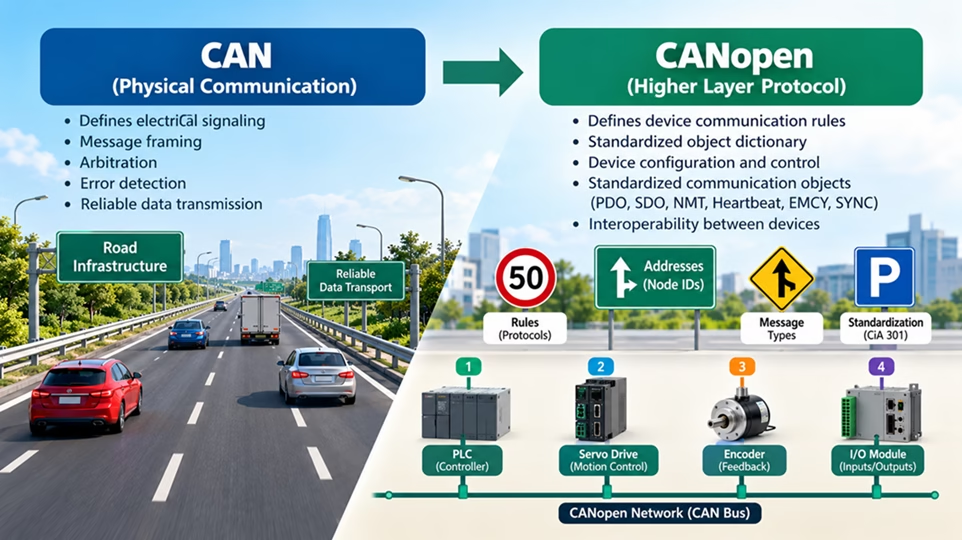
CAN sets the rules for how messages are sent through electrical signals and how different parts use the communication line. CANopen adds on to CAN by setting the rules for how devices are known, set up, managed, watched and fixed.
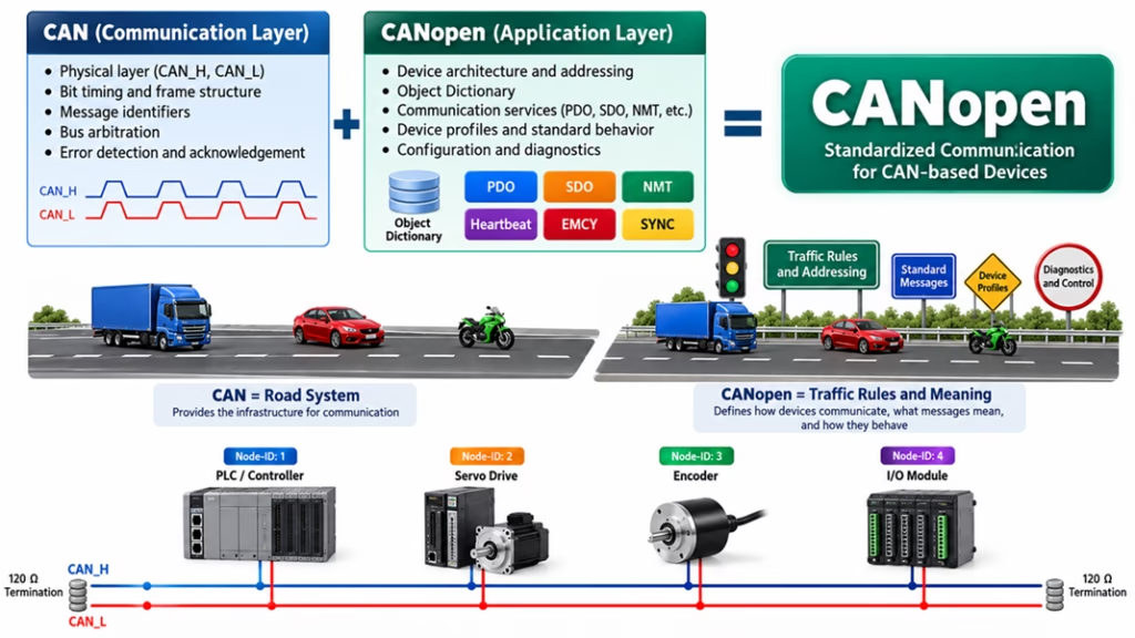
A helpful example is: CAN is, like the road system; CANopen sets the traffic rules, addresses, signs and what the vehicles traveling on the roads mean.
CANopen is widely used in automation, robotics, motion control, mobile machines, medical equipment, embedded systems and special vehicle uses.
Table of Contents
CAN vs CANopen: What Is the Difference?
CAN is primarily a communication technology. It defines concepts such as:
- CAN frames
- Message identifiers
- Bus arbitration
- Error detection
- Acknowledgement
- Physical communication using CAN_H and CAN_L
However, CAN itself does not define what a particular message means. For example, CAN-ID 0x182 has no universal meaning in raw CAN.
CANopen adds standardized communication rules on top of CAN so that devices from different manufacturers can follow a common architecture. The core CANopen communication profile is defined by CiA 301, published by CAN in Automation.
CANopen Network Architecture
A CANopen network consists of multiple devices called nodes. Each node normally has a unique Node-ID, typically between 1 and 127.
A simple industrial network could look like this:
| Node-ID | Device |
| 1 | PLC/Controller |
| 2 | Servo Drive |
| 3 | Encoder |
| 4 | I/O Module |
Every device is connected to the same CAN bus. Messages are identified using CAN identifiers, while CANopen defines their function.
Major CANopen communication services include:
- PDO — Process Data Object
- SDO — Service Data Object
- NMT — Network Management
- Heartbeat
- EMCY — Emergency message
- SYNC — Synchronization
The Object Dictionary
One of the most important CANopen concepts is the Object Dictionary. The Object Dictionary is a structured collection of parameters inside every CANopen device. It contains communication settings, configuration data, status information and application-specific values. Objects are addressed using a 16-bit index and sometimes an 8-bit sub-index.
Examples include:
| Index | Object | Function |
| 0x1000 | Device Type | Identifies the device |
| 0x1001 | Error Register | Reports error conditions |
| 0x1017 | Producer Heartbeat Time | Configures heartbeat timing |
| 0x1018 | Identity Object | Contains device identity |
A manufacturer may also define device-specific objects. For example, a motor drive might contain objects for target speed, motor current, temperature, acceleration and operating mode.
Process Data Objects: PDO
A Process Data Object (PDO) is used for fast transmission of operational data.
There are two types:
TPDO — Transmit PDO: Data sent by a node.
RPDO — Receive PDO: Data received by a node.
Suppose a motor controller needs to transmit:
- Motor speed
- Motor current
- Temperature
- Status
These values can be mapped into a PDO and transmitted efficiently without requiring another device to request each value individually. Using the predefined connection set, TPDO1 normally uses:
CAN-ID = 0x180 + Node-ID
For Node-ID 2:
0x180 + 0x02 = 0x182
Therefore, CAN-ID 0x182 normally represents TPDO1 from Node 2. PDOs are particularly useful for time-critical control data.
Service Data Objects: SDO
A Service Data Object (SDO) allows another device to read or modify entries in the Object Dictionary. SDO communication normally follows a client-server model.
For the default SDO server:
Client → Server = 0x600 + Node-ID
Server → Client = 0x580 + Node-ID
For Node 2:
Request = 0x602
Response = 0x582
Imagine that a controller needs to change the motor acceleration parameter.
The process is:
- Controller sends an SDO write request.
- The message identifies the Object Dictionary index and sub-index.
- The motor drive stores the new value.
- The drive sends an SDO response confirming the operation.
A simple rule for beginners is:
PDO = fast process data
SDO = configuration and parameter access
CANopen Network Management
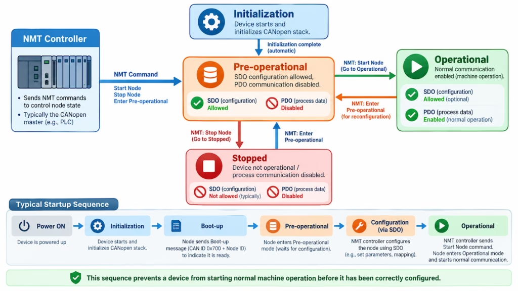
CANopen uses Network Management (NMT) to control the operational state of nodes.
Important states include:
- Initialization
- Pre-operational
- Operational
- Stopped
After power-up, a CANopen node initializes and normally enters the Pre-operational state. During Pre-operational mode, configuration using SDOs is possible, but normal PDO communication is generally disabled.
After configuration, the NMT controller can command the device to enter Operational mode.
A typical sequence is:
Power ON → Initialization → Boot-up → Pre-operational → Configuration → Operational
This prevents a device from beginning normal machine operation before it has been correctly configured.
Heartbeat Monitoring
CANopen provides Heartbeat communication to monitor whether nodes are alive. A node configured as a heartbeat producer periodically sends its current NMT state.
The default heartbeat CAN-ID is:
0x700 + Node-ID
For Node 2:
0x702
A controller can monitor these messages.
If Node 2 is configured to send a heartbeat every 500 ms but the controller stops receiving them, it can determine that the node may have failed, lost power or become disconnected. This is important for machine diagnostics and fault handling.
Emergency Messages
CANopen devices can immediately report serious faults using Emergency messages, usually called EMCY messages. Typical faults include:
- Motor overtemperature
- Overcurrent
- Voltage problems
- Encoder failure
- Internal hardware errors
The predefined EMCY CAN-ID is:
0x080 + Node-ID
For Node 2:
0x082
An EMCY frame contains an emergency error code, an error register and additional manufacturer-specific diagnostic information. Because EMCY communication is event-driven, the controller can respond quickly to important faults.
Step-by-Step CANopen Startup Example
Consider a controller communicating with a servo drive configured as Node 2.
Step 1: Connect the CAN network
Connect CAN_H and CAN_L between the devices. Correct bus termination, normally 120 Ω at each physical end of the CAN bus, is essential. Proper wiring and termination help prevent signal reflections and communication errors on the CAN bus.
Step 2: Configure the bitrate
All devices must use the same CAN bitrate. If even one node is configured with a different bitrate, it will not be able to communicate correctly with the rest of the network.
Step 3: Power the servo drive
The drive initializes its hardware, CAN controller, CANopen stack and Object Dictionary. During this initialization phase, the device prepares its communication parameters and internal CANopen services.
Step 4: Detect boot-up
After initialization, the device normally transmits a boot-up message using CAN-ID 0x702. This message informs the controller that Node 2 has completed initialization and entered the Pre-operational state.
Step 5: Configure the device
The controller uses SDO messages on 0x602 and 0x582 to read or change parameters. Typical configuration parameters may include operating modes, acceleration limits, heartbeat timing and other device-specific settings.
Step 6: Configure PDOs
Required process variables such as speed, position and status can be mapped into PDOs. PDO mapping determines which Object Dictionary values are exchanged efficiently during real-time communication.
Step 7: Start the node
The controller sends an NMT command requesting Node 2 to enter Operational state. Once the node becomes Operational, it can begin normal PDO-based process communication.
Step 8: Exchange process data
The controller and drive now exchange PDOs during normal operation. For example, the controller may send target speed commands while the drive continuously returns actual speed and status information.
Step 9: Monitor the network
Heartbeat messages confirm that the node remains active. EMCY messages indicate serious errors. The controller can use these diagnostic messages to detect failures quickly and take appropriate corrective or safety actions.
Practical Troubleshooting in CANopen
Several problems appear frequently during CANopen commissioning.
| Problem | Possible Cause |
| No communication | Incorrect bitrate or wiring |
| Intermittent errors | Missing or incorrect termination |
| Wrong device responding | Duplicate Node-ID |
| PDO not received | Node not Operational or incorrect PDO configuration |
| SDO failure | Invalid index, sub-index or access permission |
| Missing heartbeat | Incorrect heartbeat configuration or failed node |
A CANanalyzer is extremely useful because it allows engineers to inspect CAN identifiers, data bytes, timing, bus load, SDO transactions, PDOs, heartbeat messages and EMCY frames.
EDS Files
An Electronic Data Sheet (EDS) describes the CANopen capabilities and Object Dictionary of a device. Configuration software can use the EDS file to understand which parameters exist, their data types, default values, access permissions and communication settings. This makes EDS files particularly useful when configuring devices from different manufacturers.
Final Thoughts
CANopen transforms the basic CAN communication mechanism into a structured and standardized framework for device communication, configuration, control, and diagnostics. Its design makes complex multi-device networks easier to manage by assigning clear responsibilities to each communication service.
The key concepts can be summarized simply:
Object Dictionary stores device parameters.
SDO reads and writes those parameters.
PDO exchanges fast process data.
NMT controls device states.
Heartbeat monitors device availability.
EMCY reports critical faults.
For beginners, the most effective learning path is to first understand basic CAN frames and identifiers, then move on to the Object Dictionary and SDO communication, followed by PDO mapping, NMT states, heartbeat monitoring, and finally real CAN bus traces.
Once these fundamentals are understood, CANopen becomes much easier to analyze, configure, and troubleshoot in real applications. With practical experience, engineers can use CANopen to build reliable and scalable communication networks for industrial automation, robotics, motion control, embedded systems, and other CAN-based applications.